CAMSHAFT REMOVAL
PROCEDURE
-
REMOVE TIMING CHAIN COVER ASSEMBLY
-
REMOVE MANIFOLD STAY
-
REMOVE EXHAUST MANIFOLD CONVERTER SUB-ASSEMBLY
-
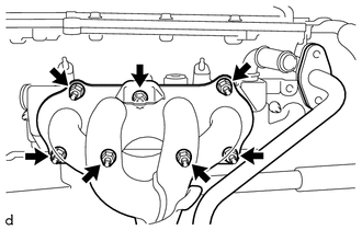
Remove the 7 nuts and exhaust manifold converter sub-assembly from the exhaust cooler assembly.
-
-
INSTALL EXHAUST MANIFOLD GASKET
-
REMOVE EXHAUST COOLER ASSEMBLY
-
REMOVE EXHAUST MANIFOLD TO HEAD GASKET
-
REMOVE NO. 1 CHAIN TENSIONER ASSEMBLY
-
REMOVE NO. 2 CHAIN VIBRATION DAMPER
-
REMOVE TIMING CHAIN TENSION ARM
-
REMOVE CHAIN SUB-ASSEMBLY
-
REMOVE TIMING CHAIN GUIDE
-
INSPECT CAMSHAFT TIMING EXHAUST GEAR ASSEMBLY
-
Check that the camshaft timing exhaust gear assembly is locked.
-
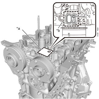
*a Adhesive Tape *b Adhesive Tape Sealing Area *c Prick a Hole After cleaning and degreasing the VVT oil hole on the exhaust side of the camshaft bearing cap, completely seal the oil hole with adhesive tape or equivalent as shown in the illustration to prevent air from leaking.
Note
Be sure to cover the oil hole completely because air leaks due to insufficient sealing will prevent the lock pin from being released.
-
Prick a hole in the tape covering the oil hole as shown in the illustration.
-
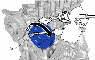
*a Protective Tape Apply approximately 200 kPa (2.0 kgf/cm2, 29 psi) of air pressure to the hole to release the lock pin.
Note
-
If air leaks out, reattach the adhesive tape.
-
Cover the oil hole with a piece of cloth when applying air pressure to prevent oil from spraying.
-
-
Using a screwdriver with its tip wrapped with protective tape, forcibly turn the camshaft timing exhaust gear assembly in the retard direction (clockwise).
Note
-
Be sure to keep the camshaft timing exhaust gear assembly in the retard direction using a screwdriver. If the camshaft timing exhaust gear assembly is released, it will return to the most advanced position automatically due to the force from the spring.
-
Do not damage the camshaft timing exhaust gear assembly.
-
-
Turn the camshaft timing exhaust gear assembly within its movable range (24 to 26°) 2 or 3 times, but do not turn it to the most retarded position. Make sure that the camshaft timing exhaust gear assembly turns smoothly.
-
Remove the adhesive tape from the camshaft bearing cap.
-
-
REMOVE CAMSHAFT TIMING EXHAUST GEAR ASSEMBLY
-
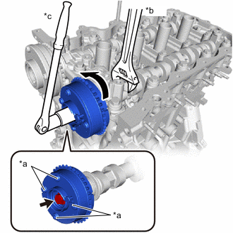
*a Do not remove *b Hold *c Turn Remove the bolt while holding the hexagonal portion of the No. 2 camshaft, and then remove the camshaft timing exhaust gear assembly from the No. 2 camshaft.
Note
-
Be sure not to remove the other 4 bolts.
-
Keep the camshaft timing exhaust gear assembly horizontal while removing it from the No. 2 camshaft.
-
-
-
REMOVE CAMSHAFT TIMING GEAR ASSEMBLY
-
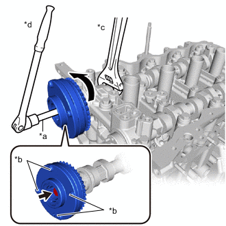
*a 10 mm Bi-hexagon Wrench *b Do not remove *c Hold *d Turn Using a 10 mm bi-hexagon wrench, remove the bolt while holding the hexagonal portion of the camshaft, and then remove the camshaft timing gear assembly from the camshaft.
Note
-
Be sure not to remove the other 4 bolts.
-
Keep the camshaft timing gear assembly horizontal while removing it from the camshaft.
-
-
-
INSPECT CAMSHAFT TIMING GEAR ASSEMBLY
-
REMOVE CAMSHAFT BEARING CAP
-
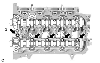
Uniformly loosen and remove the 5 bolts from the camshaft housing sub-assembly, in the order shown in the illustration.
-
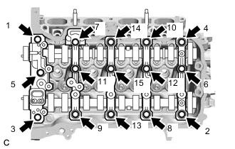
Uniformly loosen and remove the 15 bolts from the cylinder head sub-assembly, in the order shown in the illustration.
Note
Uniformly loosen the bolts while keeping the camshaft and No. 2 camshaft level.
-
Remove the 5 camshaft bearing caps from the camshaft housing sub-assembly.
Tech Tips
Arrange the removed parts in the correct order.
-
-
REMOVE OIL CONTROL VALVE FILTER
-
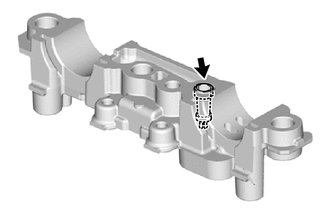
Remove the oil control valve filter from the camshaft bearing cap.
-
-
REMOVE NO. 2 CAMSHAFT
-
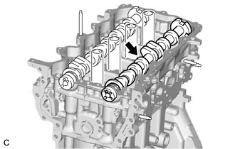
Remove the No. 2 camshaft from the camshaft housing sub-assembly.
-
-
REMOVE CAMSHAFT
-
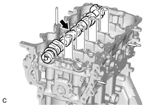
Remove the camshaft from the camshaft housing sub-assembly.
-
-
REMOVE NO. 1 VALVE ROCKER ARM SUB-ASSEMBLY
-
REMOVE VALVE LASH ADJUSTER ASSEMBLY
-
REMOVE CAMSHAFT HOUSING SUB-ASSEMBLY
-
INSPECT NO. 1 VALVE ROCKER ARM SUB-ASSEMBLY
-
INSPECT VALVE LASH ADJUSTER ASSEMBLY