CAMSHAFT INSTALLATION
CAUTION / NOTICE / HINT
Tech Tips
Perform "Inspection After Repair" after replacing the camshaft, No. 2 camshaft, camshaft timing gear assembly or camshaft timing exhaust gear assembly.
PROCEDURE
-
INSTALL VALVE LASH ADJUSTER ASSEMBLY
-
INSTALL NO. 1 VALVE ROCKER ARM SUB-ASSEMBLY
-
INSTALL CAMSHAFT
-
Clean the camshaft journals.
-
Apply a light coat of engine oil to the camshaft journals.
-
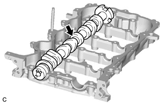
Install the camshaft to the camshaft housing sub-assembly.
-
-
INSTALL NO. 2 CAMSHAFT
-
Clean the No. 2 camshaft journals.
-
Apply a light coat of engine oil to the No. 2 camshaft journals.
-
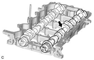
Install the No. 2 camshaft to the camshaft housing sub-assembly.
-
-
INSTALL OIL CONTROL VALVE FILTER
-
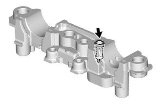
Install the oil control valve filter to the camshaft bearing cap.
-
-
INSTALL CAMSHAFT BEARING CAP
-
Apply engine oil to the camshaft bearing caps.
-
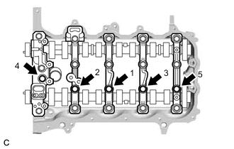
Temporarily install the 5 camshaft bearing caps to the camshaft housing sub-assembly with the 5 bolts.
-
Fully tighten the 5 bolts in the order shown in the illustration.
- Torque:
- 16 N*m { 163 kgf*cm, 12 ft.*lbf }
-
-
INSTALL CAMSHAFT HOUSING SUB-ASSEMBLY
-
INSTALL CAMSHAFT TIMING GEAR ASSEMBLY
Tech Tips
Perform "Inspection After Repair" after replacing the camshaft timing gear assembly.
-
Check that the knock pin is installed to the camshaft.
-
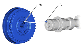
*a Knock Pin *b Knock Pin Hole Align and fit the knock pin of the camshaft to the knock pin hole of the camshaft timing gear assembly.
Note
Do not forcefully push in the camshaft timing gear assembly. This may cause the knock pin tip to damage the installation surface of the camshaft timing gear assembly.
-
Temporarily install the camshaft timing gear assembly to the camshaft with a new bolt.
-
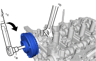
*a 10 mm Bi-hexagon Wrench *b Hold *c Turn Using a 10 mm bi-hexagon wrench, fully tighten a new bolt while holding the hexagonal portion of the camshaft.
- Torque:
- 94 N*m { 959 kgf*cm, 69 ft.*lbf }
-
-
INSTALL CAMSHAFT TIMING EXHAUST GEAR ASSEMBLY
Tech Tips
Perform "Inspection After Repairs" after replacing the camshaft timing exhaust gear assembly.
-
Check that the knock pin is installed to the No. 2 camshaft.
-
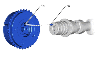
*a Knock Pin *b Knock Pin Hole Align and fit the knock pin of the No. 2 camshaft to the knock pin hole of the camshaft timing exhaust gear assembly.
Note
Do not forcefully push in the camshaft timing exhaust gear assembly. This may cause the knock pin tip to damage the installation surface of the camshaft timing exhaust gear assembly.
-
Temporarily install the camshaft timing exhaust gear assembly to the No. 2 camshaft with the bolt.
-
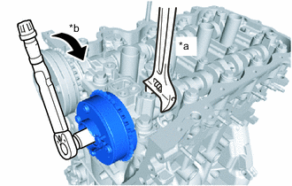
*a Hold *b Turn Fully tighten the bolt while holding the hexagonal portion of the No. 2 camshaft.
- Torque:
- 54 N*m { 551 kgf*cm, 40 ft.*lbf }
-
Make sure that the camshaft timing exhaust gear assembly is locked.
-
-
INSTALL TIMING CHAIN GUIDE
-
INSTALL CHAIN SUB-ASSEMBLY
-
INSTALL TIMING CHAIN TENSION ARM
-
INSTALL NO. 1 CHAIN TENSIONER ASSEMBLY
-
INSTALL EXHAUST MANIFOLD TO HEAD GASKET
-
INSTALL EXHAUST COOLER ASSEMBLY
-
INSTALL EXHAUST MANIFOLD GASKET
-
INSTALL EXHAUST MANIFOLD CONVERTER SUB-ASSEMBLY
-
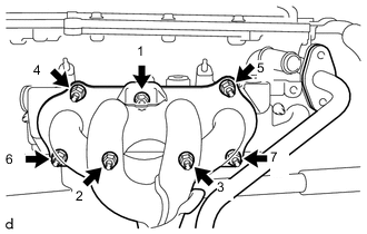
Temporarily install the exhaust manifold converter sub-assembly to the exhaust cooler assembly with 7 new nuts.
-
Fully tighten the 7 nuts in the order shown in the illustration.
- Torque:
- 26 N*m { 265 kgf*cm, 19 ft.*lbf }
-
-
INSTALL MANIFOLD STAY
-
INSTALL TIMING CHAIN COVER ASSEMBLY