PROCEDURE
- Click here
INSTALL STUD BOLT
-
Using an E8 "TORX" socket wrench, install the stud bolt to the timing chain cover assembly.
10 N*m 102 kgf*cm 7 ft.*lbf
-
- Click here
INSTALL WIRE HARNESS CLAMP BRACKET
-
Install the 2 wire harness clamp brackets to the timing chain cover assembly with the 2 bolts.
12.8 N*m 131 kgf*cm 9 ft.*lbf -
Install the wire harness clamp bracket to the cylinder block sub-assembly with the bolt.
12.8 N*m 131 kgf*cm 9 ft.*lbf -
Install the 2 wire harness clamp brackets to the cylinder head cover sub-assembly with the 2 bolts.
8.4 N*m 86 kgf*cm 74 in.*lbf
-
- Click here
INSTALL NO. 4 ENGINE WIRE
-
Connect the knock sensor connector to install the No. 4 engine wire.
-
- Click here
INSTALL NO. 1 IGNITION COIL
- Click here
INSTALL V-RIBBED BELT TENSIONER ASSEMBLY
-
Install the V-ribbed belt tensioner assembly to the timing chain cover assembly with the 2 bolts.
21 N*m 214 kgf*cm 15 ft.*lbf
-
- Click here
INSTALL NO. 1 WATER BY-PASS PIPE
-
Install the No. 1 water by-pass pipe to the cylinder block sub-assembly with the bolt.
22 N*m 224 kgf*cm 16 ft.*lbf -
Connect the No. 1 water by-pass hose to the water inlet with thermostat sub-assembly and slide the hose clip to secure it.
-
- Click here
INSTALL NO. 2 WATER BY-PASS PIPE
-
Install the No. 2 water by-pass pipe and wire harness clamp bracket to the cylinder head cover sub-assembly with the bolt and nut.
10 N*m 102 kgf*cm 7 ft.*lbf -
Connect the No. 6 water by-pass hose to the No. 1 water by-pass pipe and slide the hose clip to secure it.
-
- Click here
INSTALL NO. 6 ENGINE WIRE
-
Engage the 4 clamps to install the No. 6 engine wire to the wire harness clamp bracket and cylinder head cover sub-assembly.
-
Connect the 4 fuel injector assembly connectors.
-
- Click here
INSTALL NO. 1 INTAKE MANIFOLD TO HEAD GASKET
- Click here
INSTALL INTAKE MANIFOLD
-
Clean and degrease the bolt thread and bolt hole.
Note:Do not apply oil to the bolts.
-
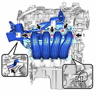
Temporarily install the intake manifold to the cylinder head sub-assembly with the 3 bolts and 2 nuts.
-
Tighten the 3 bolts and 2 nuts in the order shown in the illustration.
24 N*m 245 kgf*cm 18 ft.*lbf -
Connect the water by-pass hose to the cylinder head sub-assembly and slide the hose clip to secure it.
-
Engage the clamp to connect the No. 4 engine wire connector to the intake manifold.
-
- Click here
INSTALL PURGE VALVE (PURGE VSV)
-
Install the purge valve (purge VSV) to the intake manifold with the bolt.
10 N*m 102 kgf*cm 7 ft.*lbf -
Connect the No. 2 fuel vapor feed hose to the purge valve (purge VSV).
-
- Click here
INSTALL EGR INLET GASKET
-
Install a new EGR inlet gasket to the intake manifold.
-
- Click here
INSTALL EGR VALVE ASSEMBLY
-
Temporarily install the EGR valve assembly together with the EGR cooler assembly and EGR pipe assembly to the cylinder head sub-assembly and intake manifold with the bolt and 2 nuts.
-
Temporarily install the EGR valve bracket to the EGR valve assembly, EGR cooler assembly, camshaft housing sub-assembly and timing chain cover assembly with the 2 bolts and 2 nuts.
-
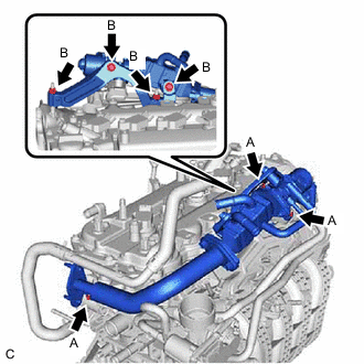
Tighten the 3 bolts and 4 nuts.
Bolt (A), Nut (A) 10 N*m 102 kgf*cm 7 ft.*lbf Bolt (B), Nut (B) 20 N*m 204 kgf*cm 15 ft.*lbf -
Engage the clamp to connect the No. 2 water by-pass hose to the hose clamp.
-
Connect the No. 2 water by-pass hose to the EGR valve assembly and slide the hose clip to secure it.
-
Connect the No. 4 water by-pass hose to the EGR cooler assembly and slide the hose clip to secure it.
-
- Click here
INSTALL VENTILATION HOSE ASSEMBLY
-
Install the ventilation hose assembly to the cylinder head cover sub-assembly, EGR cooler assembly and intake manifold and slide the 3 hose clips to secure it.
-
Engage the clamp to connect the ventilation hose assembly to the hose clamp.
-
- Click here
INSTALL EGR PIPE GASKET
- Click here
INSTALL EXHAUST MANIFOLD TO HEAD GASKET
- Click here
INSTALL EXHAUST COOLER ASSEMBLY
- Click here
INSTALL EXHAUST MANIFOLD GASKET
- Click here
INSTALL EXHAUST MANIFOLD CONVERTER SUB-ASSEMBLY
- Click here
INSTALL MANIFOLD STAY