CYLINDER HEAD REASSEMBLY

PROCEDURE
-
INSTALL SPARK PLUG TUBE
Tech Tips
When replacing the cylinder head with a new one, perform the following procedure.
-
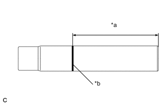
Text in Illustration *a Protrusion Height *b Mark Using paint, mark the standard position from the edge.
Standard protrusion height 88.7 to 90.2 mm (3.492 to 3.551 in.) -
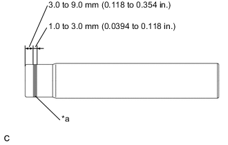
Text in Illustration *a Adhesive Apply adhesive to the spark plug tube where it will be pressed into the cylinder head.
Adhesive Toyota Genuine Adhesive 1324, Three Bond 1386D or equivalent -
Using a press and wooden block, install the spark plug tube to the required protrusion height.
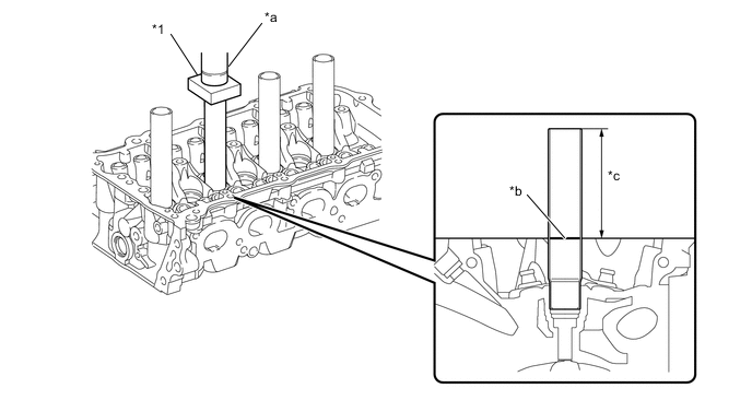
Text in Illustration *1 Wooden Block *a Press *b Mark *c Protrusion Height Standard protrusion height 88.7 to 90.2 mm (3.492 to 3.551 in.) Note
-
Install the spark plug tube within 3 minutes after applying adhesive.
-
Do not start the engine within 1 hour after installation.
-
Do not deform the spark plug tube.
-
Be careful not to drip the adhesive.
-
-
-
INSTALL VALVE SPRING SEAT
-
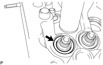
Install the valve spring seats to the cylinder head.
-
-
INSTALL VALVE STEM OIL SEAL
-
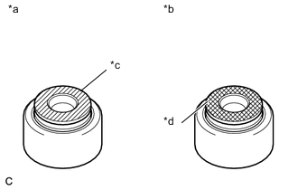
Text in Illustration *a Intake Side *b Exhaust Side *c Gray *d Black Apply a light coat of engine oil to new oil seals.
Note
Pay close attention when installing the intake and exhaust oil seals. Installing the intake oil seal into the exhaust side or installing the exhaust oil seal to the intake side may cause installation problems later.
Tech Tips
The intake valve oil seal is gray and the exhaust valve oil seal is black.
-
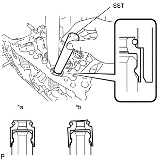
Text in Illustration *a Correct *b Incorrect Using SST, push in the oil seals.
- SST
- 09201-41020
Note
Failure to use SST may cause the oil seal to be damaged or improperly seated.
-
-
INSTALL INTAKE VALVE
Tech Tips
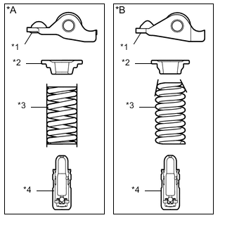
Type A and Type B can be distinguished by the shape of the outer compression spring.
Type Outer Compression Spring Shape A Straight B Taper *A Type A *B Type B *1 No. 1 Valve Rocker Arm Sub-assembly *2 Valve Spring Retainer *3 Outer Compression Spring *4 Valve Lash Adjuster Assembly
-
Type A:
-
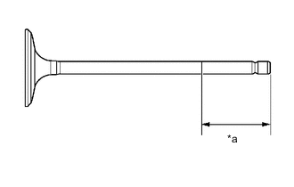
Text in Illustration *a 30 mm (1.18 in.) or more Sufficiently apply engine oil to the tip area of the intake valve shown in the illustration.
-
Install the intake valve, outer compression spring and valve spring retainer to the cylinder head sub-assembly.
Note
Install the same parts to their original positions.
-
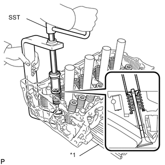
Text in Illustration *1 Wooden Block Using SST and wooden blocks, compress the outer compression spring and install the 2 valve spring retainer locks.
- SST
- 09202-70020 ( 09202-00010 )
-
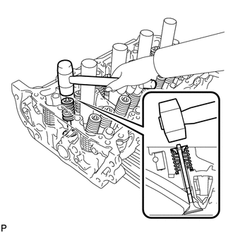
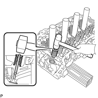
Using a plastic hammer, lightly tap the intake valve stem tip to ensure a proper fit.
Note
-
Be careful not to damage the intake valve stem tip.
-
Be careful not to tap the valve spring retainer.
-
-
-
Type B:
-
Text in Illustration *a 30 mm (1.18 in.) or more Sufficiently apply engine oil to the tip area of the intake valve shown in the illustration.
-
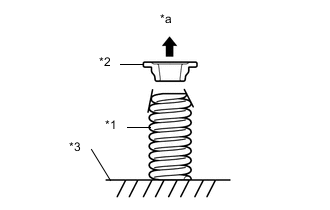
Text in Illustration *1 Outer Compression Spring *2 Valve Spring Retainer *3 Cylinder Head Sub-assembly *4 Upper Side Install the intake valve, outer compression spring and valve spring retainer to the cylinder head sub-assembly.
Note
-
Install the outer compression spring with its taper side facing upward (towards the valve spring retainer)
-
Install the same parts to their original positions.
-
-
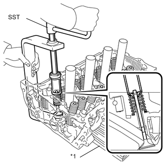
Text in Illustration *1 Wooden Block Using SST and wooden blocks, compress the outer compression spring and install the 2 valve spring retainer locks.
- SST
- 09202-70020
- 09202-00020
-
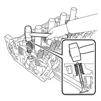
Using a plastic hammer, lightly tap the intake valve stem tip to ensure a proper fit.
Note
-
Be careful not to damage the intake valve stem tip.
-
Be careful not to tap the valve spring retainer.
-
-
-
-
INSTALL EXHAUST VALVE
Tech Tips
Type A and Type B can be distinguished by the shape of the outer compression spring.
Type Outer Compression Spring Shape A Straight B Taper *A Type A *B Type B *1 No. 1 Valve Rocker Arm Sub-assembly *2 Valve Spring Retainer *3 Outer Compression Spring *4 Valve Lash Adjuster Assembly
-
Type A:
-
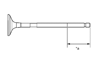
Text in Illustration *a 30 mm (1.18 in.) or more Sufficiently apply engine oil to the tip area of the exhaust valve shown in the illustration.
-
Install the exhaust valve, outer compression spring and valve spring retainer to the cylinder head sub-assembly.
Note
Install the same parts to their original positions.
-
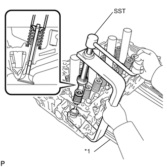
Text in Illustration *1 Wooden Block Using SST and wooden blocks, compress the outer compression spring and install the 2 valve spring retainer locks.
- SST
- 09202-70020 ( 09202-00010 )
-
Using a plastic hammer, lightly tap the exhaust valve stem tip to ensure a proper fit.
Note
-
Be careful not to damage the exhaust valve stem tip.
-
Be careful not to tap the valve spring retainer.
-
-
-
Type B:
-
Text in Illustration *a 30 mm (1.18 in.) or more Sufficiently apply engine oil to the tip area of the exhaust valve shown in the illustration.
-
Text in Illustration *1 Outer Compression Spring *2 Valve Spring Retainer *3 Cylinder Head Sub-assembly *4 Upper Side Install the exhaust valve, outer compression spring and valve spring retainer to the cylinder head sub-assembly.
Note
-
Install the outer compression spring with its taper side facing upward (towards the valve spring retainer)
-
Install the same parts to their original positions.
-
-
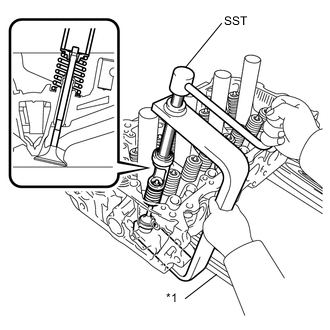
Text in Illustration *1 Wooden Block Using SST and wooden blocks, compress the outer compression spring and install the 2 valve spring retainer locks.
- SST
- 09202-70020
- 09202-00020
-
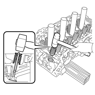
Using a plastic hammer, lightly tap the exhaust valve stem tip to ensure a proper fit.
Note
-
Be careful not to damage the exhaust valve stem tip.
-
Be careful not to tap the valve spring retainer.
-
-
-
-
INSTALL VALVE STEM CAP
-
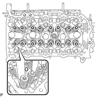
Apply a light coat of engine oil to the valve stem caps.
-
Install the valve stem caps to the cylinder head.
-