CAUTION / NOTICE / HINT
As the engine assembly with transaxle is extremely heavy, the engine lifter may suddenly drop if the instructions listed in the repair manual are not followed. Therefore, always follow the instructions listed in the repair manual when performing this procedure.
Perform "Inspection After Repairs" after replacing the engine assembly (Click here).
PROCEDURE
- Click here
INSTALL INNER OIL SEAL (w/ Stop And Start System)
- Click here
INSTALL RING GEAR SUB-ASSEMBLY (w/ Stop And Start System)
- Click here
REMOVE RING GEAR SNAP RING (w/ Stop And Start System)
- Click here
INSTALL ERS ONE-WAY CLUTCH ASSEMBLY (w/ Stop And Start System)
- Click here
INSTALL DRIVE PLATE AND RING GEAR SUB-ASSEMBLY (w/ Stop And Start System)
- Click here
INSTALL DRIVE PLATE AND RING GEAR SUB-ASSEMBLY (for CVT)
- Click here
INSTALL FLYWHEEL SUB-ASSEMBLY (for Manual Transaxle)
- Click here
INSTALL CLUTCH DISC ASSEMBLY (for Manual Transaxle)
- Click here
INSTALL CLUTCH COVER ASSEMBLY (for Manual Transaxle)
- Click here
INSTALL WATER HOSE SUB-ASSEMBLY B (for Manual Transaxle)
-
Install the water hose sub-assembly B with the clamp.
-
- Click here
INSTALL NO. 2 WATER BY-PASS PIPE SUB-ASSEMBLY (for CVT)
-
Install the No. 2 water by-pass pipe hose sub-assembly with the clamp.
-
- Click here
INSTALL WATER HOSE SUB-ASSEMBLY
-
Install the water hose sub-assembly with the clamp.
-
- Click here
INSTALL ENGINE WIRE
-
Install the engine wire to the cylinder head cover with the 2 nuts.
8.4 N*m 86 kgf*cm 74 in.*lbf -
Install the 2 ground wires to the cylinder head with the 2 bolts.
8.4 N*m 86 kgf*cm 74 in.*lbf
-
- Click here
REMOVE ENGINE HANGER
-
Remove the 2 bolts and 2 engine hangers.
-
- Click here
INSTALL MANUAL TRANSAXLE ASSEMBLY (for Manual Transaxle)
- Click here
INSTALL CONTINUOUSLY VARIABLE TRANSAXLE ASSEMBLY (for CVT)
- Click here
INSTALL DRIVE PLATE AND TORQUE CONVERTER CLUTCH SETTING BOLT (for CVT)
- Click here
INSTALL STARTER ASSEMBLY (w/ Stop And Start System)
- Click here
INSTALL STARTER ASSEMBLY (w/o Stop And Start System)
- Click here
INSTALL FLYWHEEL HOUSING SIDE COVER (w/ Stop And Start System)
- Click here
INSTALL FLYWHEEL HOUSING SIDE COVER (w/o Stop And Start System)
- Click here
INSTALL ENGINE ASSEMBLY WITH TRANSAXLE
-
Install the engine mounting insulator sub-assembly RH with the 3 bolts.
Tip:Only perform this procedure when replacement of the engine mounting insulator sub-assembly RH is necessary.
52 N*m 530 kgf*cm 38 ft.*lbf -
Install the engine mounting insulator LH with the 5 bolts.
Tip:Only perform this procedure when replacement of the engine mounting insulator LH is necessary.
52 N*m 530 kgf*cm 38 ft.*lbf -
Set the engine assembly with transaxle on the engine lifter.
-
Operate the engine lifter and lift the engine assembly with transaxle into the position where the engine mounting insulators RH and LH can be installed.
CAUTION:Do not raise the engine more than necessary. If the engine is raised excessively, the vehicle may also be lifted up.
Note:
-
Make sure that the engine is clear of all wiring and hoses.
-
While raising the engine into the vehicle, do not allow it to contact the vehicle.
-
-
Install the engine mounting insulator LH with the through bolt and nut.
52 N*m 530 kgf*cm 38 ft.*lbf -
Install the engine mounting insulator sub-assembly RH with the bolt and 2 nuts.
52 N*m 530 kgf*cm 38 ft.*lbf -
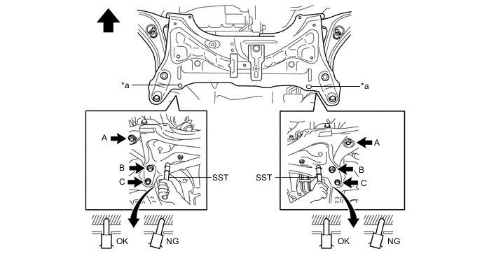
Provisionally install the front suspension crossmember onto the body with the 6 bolts.
Table 1. Text in Illustration *a Datum Hole - - 
Front of the Vehicle - - -
By inserting SST into the datum holes in the front suspension crossmember RH and LH alternately, tighten bolts A, B and C on both sides to the specified torque, in several steps.
09670-00010 Bolt A 87 N*m 887 kgf*cm 64 ft.*lbf Bolt B 151 N*m 1540 kgf*cm 111 ft.*lbf Bolt C 98 N*m 999 kgf*cm 72 ft.*lbf Note:
-
Insert SST into the datum hole in a vertical orientation.
-
If SST cannot be inserted into the datum hole vertically, loosen all the bolts and then insert SST again.
-
-
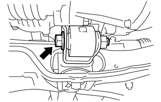
Tighten the bolt and install the engine moving control rod.
120 N*m 1224 kgf*cm 89 ft.*lbf
-
- Click here
INSTALL WIRE HARNESS CLAMP BRACKET (for Manual Transaxle)
-
Install wire harness clamp bracket with the bolt.
29 N*m 296 kgf*cm 21 ft.*lbf
-
- Click here
INSTALL WIRE HARNESS CLAMP BRACKET (for CVT)
-
Install wire harness clamp bracket with the bolt.
61 N*m 622 kgf*cm 45 ft.*lbf
-
- Click here
INSTALL DRIVE SHAFT HEAT INSULATOR SUB-ASSEMBLY
-
Install the drive shaft heat insulator sub-assembly with the 2 bolts.
24 N*m 240 kgf*cm 17 ft.*lbf
-
- Click here
INSTALL FRONT EXHAUST PIPE ASSEMBLY
-
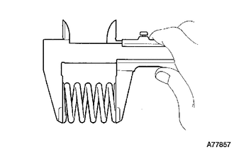
Using a vernier caliper, measure the free length of the compression springs.
Minimum length 41.5 mm (1.634 in.) If the length is not as specified, replace the compression spring.
-
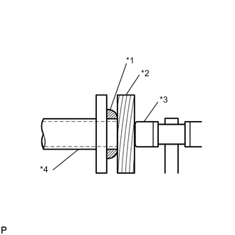
Using a plastic hammer and a wooden block, tap in a new gasket until its surface is flush with the exhaust manifold converter sub-assembly.
Table 2. Text in Illustration *1 Gasket *2 Wooden Block *3 Plastic Hammer *4 Exhaust Manifold Converter Sub-assembly Note:
-
Install the gasket in the correct direction.
-
Do not reuse the gasket.
-
Do not damage the gasket by dropping it, etc.
-
Do not damage the outer surface of the gasket.
-
Do not push in the gasket with the exhaust pipe when connecting its.
-
-
Hang the front exhaust pipe assembly with the 3 exhaust pipe supports.
-
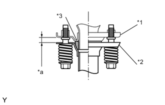
Install the front exhaust pipe sub-assembly to the exhaust manifold converter sub-assembly with the 2 compression springs and 2 bolts.
43 N*m 438 kgf*cm 32 ft.*lbf Note:After the installation, check that the gaps between the flanges of the exhaust manifold converter sub-assembly and front exhaust pipe assembly are consistent front-to-rear and left-to-right.
Table 3. Text in Illustration *1 Exhaust Manifold Converter Sub-assembly *2 Front Exhaust Pipe Assembly *3 Gasket *a Space between flanges: 8.5 mm (0.335 in.) -
Hang the tail exhaust pipe assembly with the exhaust pipe support.
-
Install a new gasket onto the front exhaust pipe sub-assembly.
-
Install the tail exhaust pipe assembly onto the front exhaust pipe sub-assembly with the 2 compression springs and 2 bolts.
19 N*m 194 kgf*cm 14 ft.*lbf -
Connect the connector of the heated oxygen sensor.
-
Engage the clamp and connect the heated oxygen sensor wire to the wire harness clamp bracket.
-
- Click here
INSTALL FRONT FLOOR CENTER BRACE
- Click here
INSTALL FRONT DRIVE SHAFT ASSEMBLY
- Click here
INSTALL NO. 1 STEERING COLUMN HOLE COVER SUB-ASSEMBLY
- Click here
INSTALL STEERING SLIDING YOKE SUB-ASSEMBLY
- Click here
INSTALL COLUMN HOLE COVER SILENCER SHEET
- Click here
CONNECT ENGINE WIRE (for Manual Transaxle)
-
Connect the connector to the negative battery terminal.
-
Connect the 2 connectors to the positive battery terminal.
-
Install the ground wire to the body with the bolt.
8.4 N*m 86 kgf*cm 74 in.*lbf -
Engage the 3 clamps and connect the connector to the engine room relay block.
-
Install the engine room relay block cover.
-
Check that the engine wire is connected between the body and engine assembly with transaxle.
-
- Click here
CONNECT ENGINE WIRE (for CVT)
-
Connect the connector to the negative battery terminal.
-
Connect the 2 connectors to the positive battery terminal.
-
Install the ground wire to the body with the bolt.
8.4 N*m 86 kgf*cm 74 in.*lbf -
Engage the 3 clamps and connect the 2 connectors to the engine room relay block.
-
Install the engine room relay block cover.
-
Check that the engine wire is connected between the body and engine assembly with transaxle.
-
- Click here
CONNECT ECM CONNECTOR (for LHD)
-
Pull down the lever to engage the lock and connect the connector to the ECM.
Note:Make sure that the levers are securely locked.
-
Engage the clamp and install the engine wire.
-
- Click here
CONNECT ECM CONNECTOR (for RHD)
-
Pull down the lever to engage the lock and connect the connector to the ECM.
Note:Make sure that the levers are securely locked.
-
- Click here
INSTALL COMPRESSOR ASSEMBLY WITH PULLEY (for TMC Made)
- Click here
INSTALL COMPRESSOR ASSEMBLY WITH PULLEY (for TMMF Made)
- Click here
INSTALL CLUTCH HOSE (for Manual Transaxle)
- Click here
CONNECT TRANSMISSION CONTROL CABLE ASSEMBLY (for Manual Transaxle)
- Click here
INSTALL TRANSMISSION CONTROL CABLE ASSEMBLY (for CVT)
- Click here
CONNECT FUEL TUBE SUB-ASSEMBLY
- Click here
INSTALL EFI FUEL PIPE CLAMP
- Click here
CONNECT WATER HOSE SUB-ASSEMBLY (for TMC Made)
- Click here
CONNECT WATER HOSE SUB-ASSEMBLY B (for TMC Made)
- Click here
CONNECT WATER HOSE SUB-ASSEMBLY (for TMMF Made)
- Click here
CONNECT WATER HOSE SUB-ASSEMBLY B (for TMMF Made)
- Click here
CONNECT NO. 2 RADIATOR HOSE
-
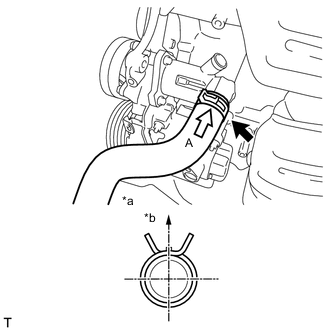
Connect the No. 2 radiator hose with the clamp.
Table 4. Text in Illustration *a View A *b Upper Side
-
- Click here
CONNECT NO. 1 RADIATOR HOSE
-
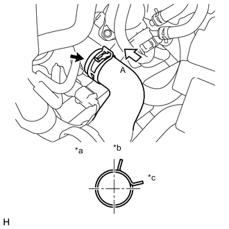
Connect the No. 1 radiator hose with the clamp.
Table 5. Text in Illustration *a View A *b Upper Side *c Rear Side
-
- Click here
CONNECT NO. 1 BREATHER PLUG (for CVT)
-
Connect the No. 1 breather plug.
-
- Click here
CONNECT UNION TO CONNECTOR TUBE HOSE
-
Connect the union to connector tube hose to the intake manifold.
-
- Click here
INSTALL AIR CLEANER AND HOSE ASSEMBLY
-
Connect the air cleaner hose to the throttle body.
-
Connect the No. 2 ventilation hose to the air cleaner hose.
-
Connect the No. 1 fuel vapor feed hose and the No. 2 fuel vapor feed hose to the No. 1 vacuum switching valve assembly.
-
Connect the No. 1 vacuum switching valve assembly connector and engage the clamp.
-
Install the air cleaner case to the cylinder head cover with the 2 bolts.
7.8 N*m 80 kgf*cm 69 in.*lbf -
Connect the intake mass air flow meter connector and engage the clamp.
-
- Click here
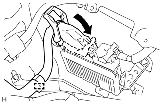
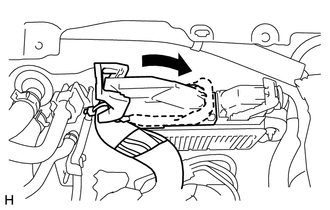
INSTALL BATTERY CARRIER
-
Install the battery carrier with the 5 bolts.
17 N*m 173 kgf*cm 13 ft.*lbf -
Engage the 3 clamps and connect the wire harness to the battery carrier.
-
- Click here
INSTALL BATTERY TRAY
-
Install the battery tray to the battery carrier.
-
- Click here
INSTALL BATTERY
-
Install the battery to the battery tray.
-
Install the battery carrier clamp with the nut.
3.5 N*m 36 kgf*cm 31 in.*lbf -
Connect the cable to the positive (+) battery terminal.
5.4 N*m 55 kgf*cm 48 in.*lbf
-
- Click here
INSTALL GENERATOR ASSEMBLY (for 80A Type)
- Click here
INSTALL GENERATOR ASSEMBLY (for 100A Type)
- Click here
INSTALL OUTER COWL TOP PANEL
- Click here
INSTALL INNER COWL TOP TO COWL BRACE
- Click here
INSTALL FRONT NO. 1 VENTILATOR SEAL
- Click here
INSTALL FRONT AIR SHUTTER SEAL RH
- Click here
INSTALL WINDSHIELD WIPER LINK ASSEMBLY
- Click here
INSTALL FRONT WHEELS
103 N*m 1050 kgf*cm 76 ft.*lbf - Click here
CONNECT CABLE TO NEGATIVE BATTERY TERMINAL
5.4 N*m 55 kgf*cm 48 in.*lbf - Click here
INSPECT SHIFT LEVER POSITION (for CVT)
- Click here
ADJUST SHIFT LEVER POSITION (for CVT)
- Click here
INSTALL REAR CONSOLE BOX ASSEMBLY (for CVT)
- Click here
ADD ENGINE OIL
- Click here
ADD ENGINE COOLANT
- Click here
ADD CONTINUOUSLY VARIABLE TRANSAXLE FLUID (for CVT)
- Click here
ADD MANUAL TRANSAXLE OIL (for Manual Transaxle)
- Click here
BLEED CLUTCH PIPE LINE (for Manual Transmission)
- Click here
INSPECT CONTINUOUSLY VARIABLE TRANSAXLE FLUID (for CVT)
- Click here
INSPECT FOR FUEL LEAK
- Click here
INSPECT ENGINE OIL LEVEL
- Click here
INSPECT FOR ENGINE OIL LEAK
- Click here
INSPECT FOR ENGINE COOLANT LEAK
- Click here
INSPECT RESERVOIR TANK ENGINE COOLANT LEVEL
- Click here
INSPECT CONTINUOUSLY VARIABLE TRANSAXLE FLUID LEAK (for CVT)
- Click here
INSPECT MANUAL TRANSAXLE OIL LEAK (for Manual Transaxle)
- Click here
INSPECT FOR CLUTCH FLUID LEAK (for Manual Transmission)
- Click here
INSPECT FOR EXHAUST GAS LEAK
Tip:Perform "Inspection After Repairs" after repairing gas leaks in the exhaust system (Click here).
- Click here
INSPECT IGNITION TIMING
- Click here
INSPECT ENGINE IDLING SPEED
- Click here
INSPECT CO/HC
- Click here
INSPECT AND ADJUST FRONT WHEEL ALIGNMENT
- Click here
INSTALL ENGINE UNDER COVER RH
5.0 N*m 51 kgf*cm 44 in.*lbf - Click here
INSTALL ENGINE UNDER COVER LH
5.0 N*m 51 kgf*cm 44 in.*lbf - Click here
CHECK ABS SENSOR SIGNAL (w/o VSC)
- Click here
CHECK VSC SENSOR SIGNAL (w/ VSC)