ENGINE UNIT INSPECTION

PROCEDURE
-
INSPECT CAMSHAFT TIMING CONTROL MOTOR WITH EDU ASSEMBLY
-
INSPECT CAMSHAFT TIMING GEAR ASSEMBLY
-
INSPECT CAMSHAFT TIMING EXHAUST GEAR ASSEMBLY
-
Check the camshaft timing exhaust gear assembly for wear or damage.
If worn or damaged, replace the camshaft timing exhaust gear assembly.
-
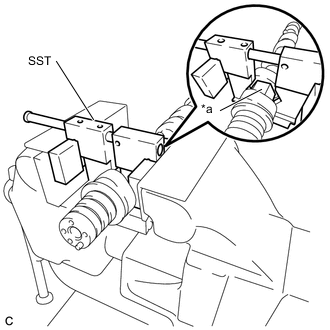
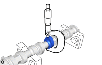
*a Hexagonal Portion Install the camshaft timing exhaust gear assembly.
-
Using SST, grip the hexagonal portion, and then secure SST and the No. 2 camshaft in a vise as shown in the illustration.
- SST
- 09212-31010
Note
-
Do not damage the No. 2 camshaft.
-
Never grip areas other than the hexagonal portion as this may cause damage.
-
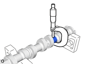
Check that the knock pin is installed to the No. 2 camshaft.
-
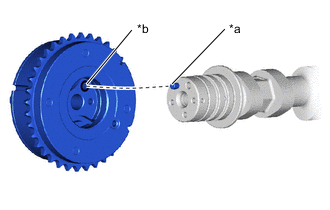
*a Knock Pin *b Knock Pin Hole Put the camshaft timing exhaust gear assembly and No. 2 camshaft together by aligning the knock pin hole and knock pin.
Note
Do not forcibly push in the camshaft timing exhaust gear assembly. Otherwise, the seal of the camshaft timing exhaust gear assembly may be damaged by the tip of the No. 2 camshaft knock pin.
-
Tighten the bolt with the camshaft timing exhaust gear assembly secured in place.
- Torque:
- 54 N*m { 551 kgf*cm, 40 ft.*lbf }
-
-
Check the camshaft timing exhaust gear assembly lock.
-
Make sure that the camshaft timing exhaust gear assembly is locked.
-
-
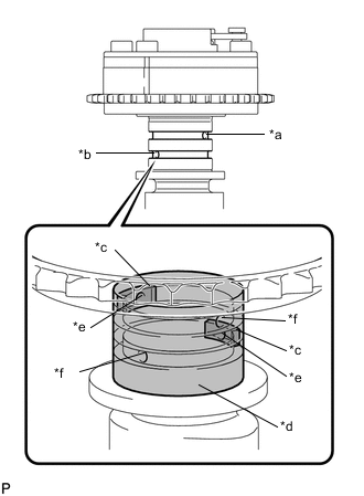
*a Advance Side Path *b Retard Side Path *c Rubber Pieces *d Vinyl Tape *e Closed *f Open Release the lock pin.
-
Cover the 4 oil paths of the cam journal with vinyl tape as shown in the illustration.
Tech Tips
The 4 oil paths are provided in the grooves. Plug 2 paths with rubber pieces.
-
Prick a hole in the tape placed on the retard side path, on the opposite side to that of the advance side path, as shown in the illustration.
-
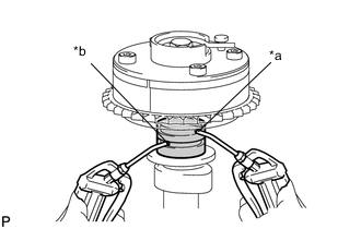
*a Advance Side Path *b Retard Side Path Apply approximately 200 kPa (2.0 kgf/cm2, 29 psi) of air pressure to the 2 paths (the advance side path and the retard side path).
Note
Cover the paths with a piece of cloth when applying pressure to keep oil from spraying.
-
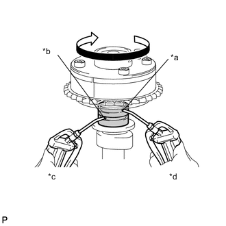
*a Advance Side Path *b Retard Side Path *c Hold Pressure *d Reduce Pressure Make sure that the camshaft timing exhaust gear assembly turns in the retard direction (clockwise) when reducing the air pressure applied to the advance side path.
Tech Tips
The lock pin is released and the camshaft timing exhaust gear assembly turns in the retard direction.
-
When the camshaft timing exhaust gear assembly moves to the most retarded position, release the air pressure from the advance side path, and then release the air pressure from the retard side path.
Note
Be sure to release the air pressure from the advance side path first. If the air pressure of the retard side path is released first, the camshaft timing exhaust gear assembly may abruptly shift in the advance direction and break the lock pin or other parts.
-
-
Check for smooth rotation.
-
Turn the camshaft timing exhaust gear assembly within its movable range (24 to 26°) 2 or 3 times, but do not turn it to the most advanced position. Make sure that the gear turns smoothly.
Note
When the air pressure is released from the advance side path, and then from the retard side path, the gear automatically returns to the most advanced position due to the advance assist spring operation and locks. Gradually release the air pressure from the retard side path before performing the smooth rotation check.
-
-
Check the lock at the most advanced position.
-
Make sure that the camshaft timing exhaust gear assembly is locked at the most advanced position.
-
-
-
INSPECT NO. 1 VALVE ROCKER ARM SUB-ASSEMBLY
-
Turn the roller by hand to check that it turns smoothly.
Tech Tips
If the roller does not turn smoothly, replace the No. 1 valve rocker arm sub-assembly.
-
-
INSPECT VALVE LASH ADJUSTER ASSEMBLY
Note
-
Keep the valve lash adjuster assembly free from dirt and foreign matter.
-
Only use clean engine oil.
-
Place the valve lash adjuster assembly into a container filled with engine oil.
-
Insert the tip of SST into the valve lash adjuster assembly plunger and use the tip to press down on the check ball inside the plunger.
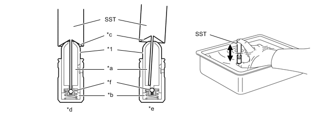
*1 Plunger - - *a Low Pressure Chamber *b High Pressure Chamber *c Tapered Path *d Correct *e Incorrect *f Check Ball - SST
- 09276-75010
-
Squeeze SST and the valve lash adjuster assembly together to move the plunger up and down 5 to 6 times.
-
Check the movement of the plunger and bleed the air.
OK Plunger moves up and down. Note
When bleeding air from the high-pressure chamber, make sure that the tip of SST is actually pressing the check ball as shown in the illustration. If the check ball is not pressed, air will not bleed.
-
After bleeding the air, remove SST. Then try to quickly and firmly press the plunger by hand.
OK Plunger is very difficult to move. Tech Tips
If the plunger moves, bleed air again.
If the plunger moves even after bleeding air 3 times, replace the valve lash adjuster assembly with a new one.
-
-
INSPECT CHAIN SUB-ASSEMBLY
-
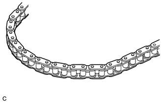
Visually check the chain sub-assembly for wear or cracks.
If the chain sub-assembly is worn or cracked, replace the chain sub-assembly and check the sprocket.
-
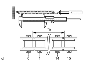
*a Measurement Area Using a spring scale, pull the chain sub-assembly with a force of 147 N (15 kgf, 33 lbf) as shown in the illustration.
-
Using a vernier caliper, measure the length of 15 pins.
Maximum Chain Sub-assembly Elongation 114.8 mm (4.52 in.) Note
Perform the measurement at 3 random places. Use the average of the measurements.
Tech Tips
If the average elongation is more than the maximum, replace the chain sub-assembly.
-
-
INSPECT CAMSHAFT TIMING GEAR ASSEMBLY
-
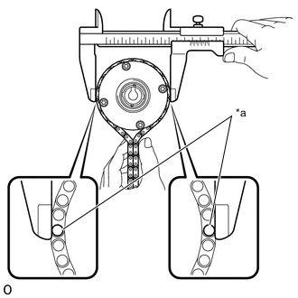
*a Chain Roller Place the chain sub-assembly around the camshaft timing gear assembly.
-
Using a vernier caliper, measure the diameter of the camshaft timing gear assembly and chain sub-assembly.
Minimum Camshaft Timing Gear Assembly Diameter (with Chain Sub-assembly) 96.8 mm (3.81 in.) Note
The vernier caliper must be in contact with the chain rollers when measuring.
Tech Tips
If the diameter is less than the minimum, replace the chain sub-assembly and camshaft timing gear assembly.
-
-
INSPECT CAMSHAFT TIMING EXHAUST GEAR ASSEMBLY
-
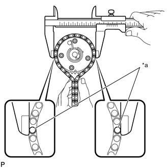
*a Chain Roller Place the chain sub-assembly around the camshaft timing exhaust gear assembly.
-
Using a vernier caliper, measure the diameter of the camshaft timing exhaust gear assembly and chain sub-assembly.
Minimum Camshaft Timing Exhaust Gear Assembly diameter (with Chain Sub-assembly) 96.8 mm (3.81 in.) Note
The vernier caliper must be in contact with the chain rollers when measuring.
Tech Tips
If the diameter is less than the minimum, replace the chain sub-assembly and camshaft timing exhaust gear assembly.
-
-
INSPECT CRANKSHAFT TIMING SPROCKET
-
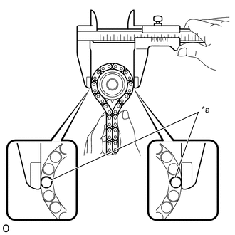
*a Chain Roller Place the chain sub-assembly around the crankshaft timing sprocket.
-
Using a vernier caliper, measure the crankshaft timing sprocket diameter with the chain sub-assembly.
Minimum Crankshaft Timing Sprocket Diameter (with Chain Sub-assembly) 51.1 mm (2.01 in.) Note
The vernier caliper must be in contact with the chain rollers when measuring.
Tech Tips
If the diameter is less than the minimum, replace the chain sub-assembly and crankshaft timing sprocket.
-
-
INSPECT TIMING CHAIN TENSION ARM
-
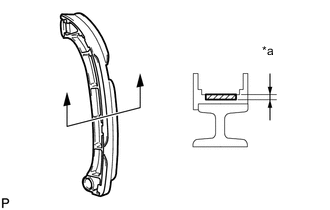
*a Depth Using a vernier caliper, measure the wear depth of the gear or timing chain tension arm.
Maximum Depth 1.0 mm (0.0394 in.) Tech Tips
If the depth is less than the minimum, replace the timing chain tension arm.
-
-
INSPECT TIMING CHAIN GUIDE
-
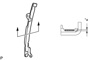
*a Depth Using a vernier caliper, measure wear depth of the timing chain guide.
Maximum Depth 1.0 mm (0.0394 in.) Tech Tips
If the depth is less than the minimum, replace the timing chain guide.
-
-
INSPECT NO. 2 CHAIN VIBRATION DAMPER
-
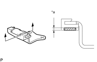
*a Depth Using a vernier caliper, measure the wear depth of the No. 2 chain vibration damper.
Maximum Depth 1.0 mm (0.0394 in.) Tech Tips
If the depth is less than the minimum, replace the No. 2 chain vibration damper.
-
-
INSPECT NO. 1 CHAIN TENSIONER ASSEMBLY
-
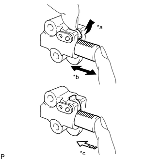
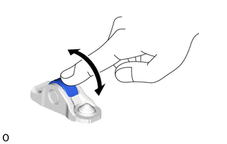
*a Raise *b Move *c Lock Move the stopper plate counterclockwise to release the lock. Push the plunger and check that it moves smoothly.
-
Release the cam, then check that the plunger is locked in place by the cam and does not move when pushed with your finger.
Tech Tips
If the plunger does not move smoothly, replace the No. 1 chain tensioner assembly.
-
-
INSPECT CAMSHAFT
-
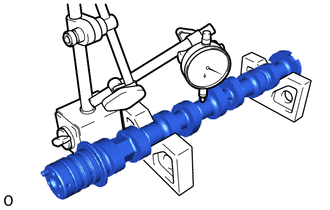
Inspect the camshaft for runout.
-
Place the camshaft on V-blocks.
-
Using a dial indicator, measure the runout at the center journal.
Maximum Runout 0.04 mm (0.00157 in.) Tech Tips
If the runout is more than the maximum, replace the camshaft.
-
-
Inspect the cam lobes.
-
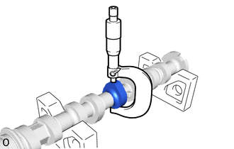
Using a micrometer, measure the cam lobe height.
Standard Cam Lobe Height 41.700 to 41.800 mm (1.64173 to 1.64567 in.) Minimum Cam Lobe Height 41.650 mm (1.63976 in.) Tech Tips
If the cam lobe height is less than the minimum, replace the camshaft.
-
-
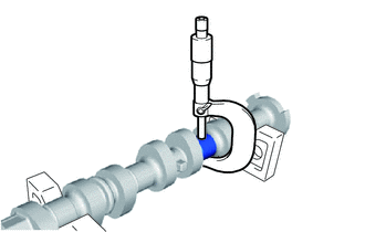
Inspect the camshaft journals.
-
Using a micrometer, measure the journal diameter.
Standard Journal Diameter Item Specified Condition No. 1 journal 34.454 to 34.470 mm (1.35645 to 1.35708 in.) Other journals 22.954 to 22.970 mm (0.90370 to 0.90433 in.)
-
-
-
INSPECT NO. 2 CAMSHAFT
-
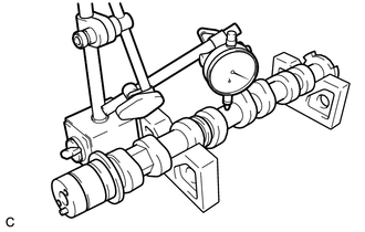
Inspect the No. 2 camshaft for runout.
-
Place the No. 2 camshaft on V-blocks.
-
Using a dial indicator, measure the runout at the center journal.
Maximum Runout 0.04 mm (0.00157 in.) Tech Tips
If the runout is more than the maximum,replace the No. 2 camshaft.
-
-
Inspect the cam lobes.
-
Using a micrometer, measure the cam lobe height.
Standard Cam Lobe Height 40.760 to 40.860 mm (1.60472 to 1.60866 in.) Minimum Cam Lobe Height 40.610 mm (1.59882 in.) Tech Tips
If the cam lobe height is less than the minimum, replace the No. 2 camshaft.
-
-
Inspect the No. 2 camshaft journals.
-
Using a micrometer, measure the journal diameter.
Standard Journal Diameter Item Specified Condition No. 1 journal 34.454 to 34.470 mm (1.35645 to 1.35708 in.) Other journal 22.954 to 22.970 mm (0.90370 to 0.90433 in.) Tech Tips
If the journal diameter is not as specified, check the No. 2 camshaft oil clearance.
-
-
-
INSPECT CYLINDER HEAD SET BOLT
-
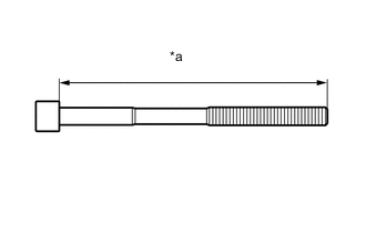
*a Measurement Length Using a vernier caliper, measure the length of the cylinder head set bolt from the seat to the end.
Standard Cylinder Head Set Bolt Length 125.3 to 126.7 mm (4.93 to 4.99 in.) Maximum Cylinder Head Set Bolt Length 128.2 mm (5.05 in.) If the length is more than the maximum, replace the cylinder head set bolt with a new one. Failure to do so may lead to engine damage.
If there is any thread deformation, replace the cylinder head set bolt with a new one.
-