ENGINE UNIT DISASSEMBLY

PROCEDURE
-
REMOVE FUEL DELIVERY PIPE
-
Make sure that there are no deposits such as sand or grit near the fuel injector assembly, and if there are any deposits, clean them away.
Note
Do not allow foreign matter to enter any other components.
-
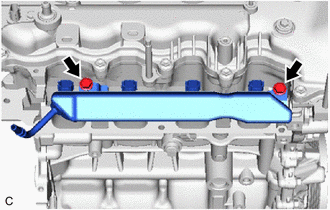
Remove the 2 bolts and fuel delivery pipe together with the 4 fuel injector assemblies from the cylinder head sub-assembly.
Note
-
Do not allow foreign matter to enter the cylinder head sub-assembly.
-
Do not drop the fuel injector assembly.
-
-
-
REMOVE NO. 1 DELIVERY PIPE SPACER
-
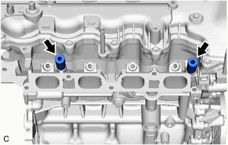
Remove the 2 No. 1 delivery pipe spacers from the cylinder head sub-assembly.
-
-
REMOVE INJECTOR VIBRATION INSULATOR
-
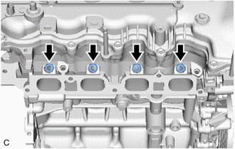
Remove the 4 injector vibration insulators from the cylinder head sub-assembly.
-
-
REMOVE FUEL INJECTOR ASSEMBLY
-
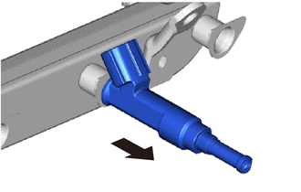
Pull the 4 fuel injector assemblies out of the fuel delivery pipe.
Note
Do not allow foreign matter to enter the fuel delivery pipe.
-
Remove the O-ring from each fuel injector assembly.
Note
-
Attach a tag or label with the corresponding cylinder number to each fuel injector assembly so that they can be installed to their original locations.
-
Protect the fuel injector assemblies by covering them with plastic bags.
-
-
-
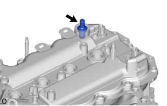
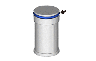
REMOVE OIL FILLER CAP ASSEMBLY
-
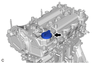
Remove the oil filler cap assembly from the cylinder head cover sub-assembly.
-
-
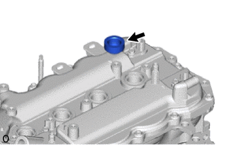
REMOVE OIL FILLER CAP GASKET
-
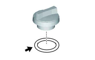
Remove the oil filler cap gasket from the oil filler cap assembly.
-
-
REMOVE SPARK PLUG
-
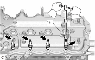
*a 14 mm Spark Plug Wrench Using a 14 mm spark plug wrench, remove the 4 spark plugs from the cylinder head sub-assembly.
Note
If a spark plug has been struck or dropped, replace it.
-
-
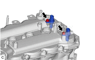
REMOVE CAMSHAFT TIMING OIL CONTROL VALVE ASSEMBLY
-
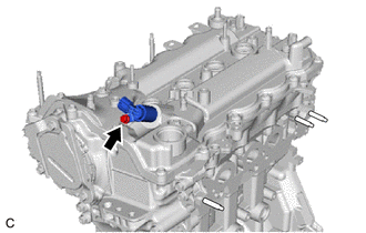
Remove the bolt and camshaft timing oil control valve assembly from the cylinder head cover sub-assembly.
Note
-
Do not allow foreign matter to contact the oil seal face of the camshaft timing oil control valve assembly (connecting surface with the cylinder head cover sub-assembly).
-
If the camshaft timing oil control valve assembly has been struck or dropped, replace it.
-
-
-
REMOVE CAMSHAFT TIMING OIL CONTROL VALVE O-RING
Tech Tips
This procedure is performed when the camshaft timing oil control valve O-ring must be replaced with a new one.
-
Remove the camshaft timing oil control valve O-ring from the camshaft timing oil control valve assembly.
-
-
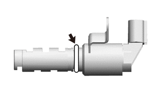
REMOVE PCV VALVE (VENTILATION VALVE SUB-ASSEMBLY)
-
Remove the PCV valve (ventilation valve sub-assembly) from the ventilation system grommet.
-
-
REMOVE VENTILATION SYSTEM GROMMET
-
Remove the ventilation system grommet from the cylinder head cover sub-assembly.
-
-
REMOVE CAMSHAFT TIMING CONTROL MOTOR WITH EDU ASSEMBLY
-
REMOVE CAMSHAFT TIMING CONTROL MOTOR O-RING
-
REMOVE CAMSHAFT POSITION SENSOR
-
Remove the 2 bolts and 2 camshaft position sensors from the cylinder head cover sub-assembly.
Note
If the camshaft position sensor has been struck or dropped, replace it.
-
-
REMOVE CYLINDER HEAD COVER SUB-ASSEMBLY
-
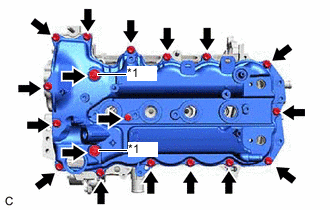
*1 Seal Washer and Plate Washer Remove the 18 bolts, 2 seal washers, 2 plate washers and cylinder head cover sub-assembly from the camshaft housing sub-assembly.
Note
Be careful not to drop the camshaft bearing cap oil hole gasket into the engine when removing the cylinder head cover sub-assembly because the the camshaft bearing cap oil hole gasket may stick to the cylinder head cover sub-assembly.
-
-
REMOVE CYLINDER HEAD COVER GASKET
-
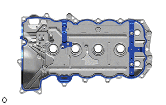
Remove the cylinder head cover gasket from the cylinder head cover sub-assembly.
-
-
REMOVE CAMSHAFT BEARING CAP OIL HOLE GASKET
-
Remove the camshaft bearing cap oil hole gasket from the camshaft bearing cap.
-
-
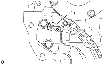
REMOVE CRANKSHAFT POSITION SENSOR
-
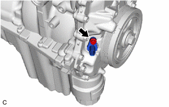
Remove the bolt and crankshaft position sensor from the timing chain cover assembly.
Note
If the crankshaft position sensor has been struck or dropped, replace it.
-
-
REMOVE ENGINE OIL PRESSURE SWITCH ASSEMBLY
-
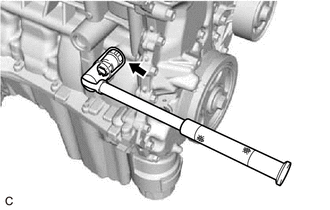
Using a 24 mm deep socket wrench, remove the engine oil pressure switch assembly from the cylinder block sub-assembly.
Note
If the engine oil pressure switch assembly has been struck or dropped, replace it.
-
-
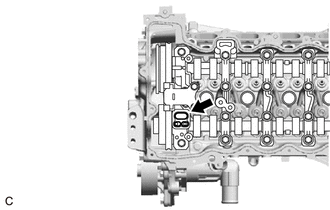
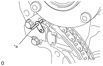
REMOVE KNOCK SENSOR
-
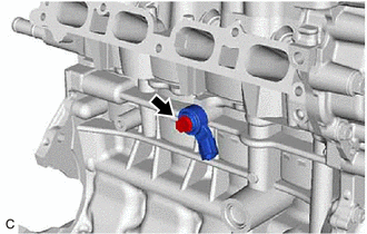
Remove the bolt and knock sensor from the cylinder block sub-assembly.
Note
If the knock sensor has been struck or dropped, replace it.
-
-
REMOVE ENGINE COOLANT TEMPERATURE SENSOR
-
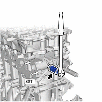
Using SST, remove the engine coolant temperature sensor and gasket from the cylinder head sub-assembly.
- SST
- 09817-33191
Note
If the engine coolant temperature sensor has been struck or dropped, replace it.
-
-
REMOVE OIL FILTER CAP ASSEMBLY
-
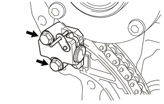
REMOVE WATER INLET WITH THERMOSTAT SUB-ASSEMBLY
-
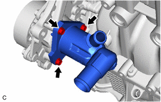
Remove the 3 bolts and water inlet with thermostat sub-assembly from the timing chain cover assembly.
-
-
REMOVE NO. 2 WATER INLET HOUSING GASKET
-
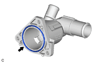
Remove the No. 2 water inlet housing gasket from the water inlet with thermostat sub-assembly.
-
-
REMOVE REAR ENGINE OIL SEAL
-
SET NO. 1 CYLINDER TO TDC/COMPRESSION
-
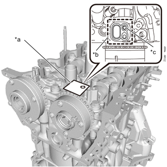
Turn the crankshaft pulley until its timing notch (groove) and timing mark (TDC) of the timing chain cover assembly are aligned.
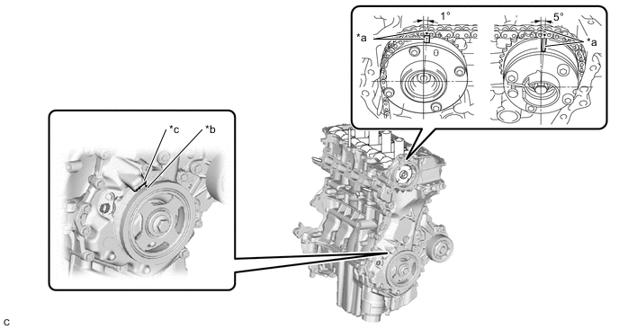
*a Timing Mark *b Timing Notch (Groove) *c Timing Mark (TDC) - - -
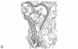
Check that each timing mark of the camshaft timing gear assembly and camshaft timing exhaust gear assembly are aligned as shown in the illustration. If not, turn the crankshaft 1 revolution (360°) to align the timing marks as shown in the illustration.
-
-
REMOVE CRANKSHAFT PULLEY
-
REMOVE ENGINE WATER PUMP ASSEMBLY
-
REMOVE TIMING CHAIN COVER ASSEMBLY
-
REMOVE TIMING CHAIN COVER OIL SEAL
-
REMOVE NO. 1 CHAIN TENSIONER ASSEMBLY
-
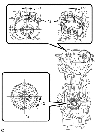
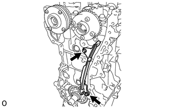
*a Timing Mark Check that the timing marks on the camshaft timing exhaust gear assembly, camshaft timing gear assembly and crankshaft are as shown in the illustration.
Tech Tips
Make sure that the timing mark of the crankshaft is positioned as shown in the illustration (20° ATDC).
-
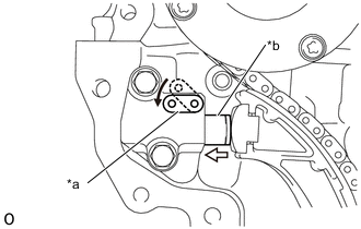
*a Stopper Plate *b Plunger 
Push Push down on the stopper plate to release the lock and push in the plunger.
-
*a Stopper Plate Pull up the stopper plate with the plunger fully pushed in.
-
*a Pin Insert a pin of φ3 mm (0.118 in.) diameter into the hole in the stopper plate to lock the plunger.
-
Remove the 2 bolts, No. 1 chain tensioner assembly and chain tensioner gasket from the cylinder head sub-assembly.
-
-
REMOVE NO. 2 CHAIN VIBRATION DAMPER
-
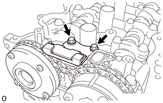
Remove the 2 bolts and No. 2 chain vibration damper from the camshaft bearing cap.
-
-
REMOVE TIMING CHAIN TENSION ARM
-
Remove the timing chain tension arm from the cylinder block sub-assembly.
-
-
REMOVE CHAIN SUB-ASSEMBLY
-
Remove the chain sub-assembly.
-
-
REMOVE TIMING CHAIN GUIDE
-
Remove the 2 bolts and timing chain guide from the cylinder head sub-assembly and cylinder block sub-assembly.
-
-
REMOVE CRANKSHAFT TIMING SPROCKET
-
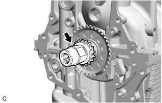
Remove the crankshaft timing sprocket from the crankshaft.
-
-
REMOVE CRANKSHAFT TIMING GEAR KEY
-
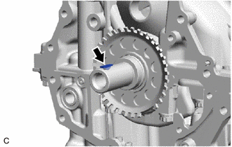
Remove the crankshaft timing gear key from the crankshaft.
-
-
INSPECT CAMSHAFT TIMING EXHAUST GEAR ASSEMBLY
-
*a Adhesive Tape *b Adhesive Tape Sealing Area *c Prick a Hole Check the lock of the camshaft timing exhaust gear assembly.
-
After cleaning and degreasing the VVT oil hole on the exhaust side of the camshaft bearing cap, completely seal the oil hole with adhesive tape or equivalent as shown in the illustration to prevent air from leaking.
Note
Be sure to cover the oil hole completely because air leaks due to insufficient sealing will prevent the lock pin from being released.
-
Prick a hole in the tape covering the oil hole as shown in the illustration. (Procedure A)
-
*a Protective Tape Apply compressed air at approximately 200 kPa (2.0 kgf/cm2, 28 psi) to the hole pricked in procedure A to release the lock pin.
Note
-
If air leaks out, reattach the adhesive tape.
-
Cover the oil hole with a piece of cloth when applying compressed air to prevent oil from spraying.
-
-
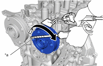
Using a screwdriver with its tip wrapped with tape, forcibly turn the camshaft timing exhaust gear assembly in the retard direction (clockwise).
Note
-
Be sure to keep the camshaft timing exhaust gear assembly in the retard direction using a screwdriver. If the gear is released, it will return to the most advanced position automatically due to the force from the spring.
-
Do not damage the camshaft timing exhaust gear assembly.
-
-
Using a screwdriver with its tip wrapped with tape, turn the camshaft timing exhaust gear assembly within its movable range (24 to 26°) 2 or 3 times without turning it to the most advanced position. Make sure that the camshaft timing exhaust gear assembly turns smoothly.
-
Remove the adhesive tape from the camshaft bearing cap.
-
-
REMOVE CAMSHAFT TIMING EXHAUST GEAR ASSEMBLY
-
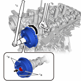
*a Do Not Remove *b Hold *c Turn Using a wrench, grip the hexagonal portion of the No. 2 camshaft.
-
Remove the bolt and camshaft timing exhaust gear assembly from the No. 2 camshaft.
Note
-
Be sure not to remove the other 4 bolts.
-
Keep the camshaft timing exhaust gear assembly horizontal while removing it from the No. 2 camshaft.
-
-
-
REMOVE CAMSHAFT TIMING GEAR ASSEMBLY
-
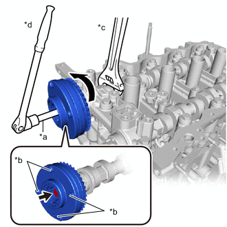
*a 10 mm Bi-hexagon Wrench *b Do Not Remove *c Hold *d Turn Using a wrench, grip the hexagonal portion of the camshaft.
-
Using a 10 mm bi-hexagonal wrench, remove the bolt and camshaft timing gear assembly from the camshaft.
Note
-
Be sure not to remove the other 4 bolts.
-
Keep the camshaft timing gear assembly horizontal while removing it from the camshaft.
-
-
-
INSPECT CAMSHAFT TIMING GEAR ASSEMBLY
-
REMOVE CAMSHAFT BEARING CAP
-
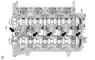
Uniformly loosen and remove the 5 bolts in the order shown in the illustration.
-
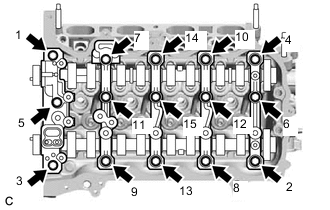
Uniformly loosen and remove the 15 bolts in the order shown in the illustration.
-
Remove the 5 camshaft bearing caps from the camshaft housing sub-assembly.
Tech Tips
Arrange the removed parts in the correct order.
-
-
REMOVE OIL CONTROL VALVE FILTER
-
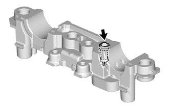
Remove the oil control valve filter from the camshaft bearing cap.
-
-
REMOVE NO. 2 CAMSHAFT
-
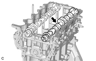
Remove the No. 2 camshaft from the camshaft housing sub-assembly.
-
-
REMOVE CAMSHAFT
-
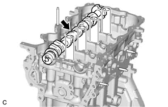
Remove the camshaft from the camshaft housing sub-assembly.
-
-
REMOVE NO. 1 VALVE ROCKER ARM SUB-ASSEMBLY
-
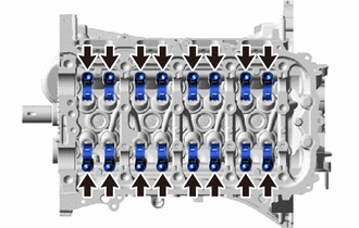
Remove the 16 No. 1 valve rocker arm sub-assemblies from the cylinder head sub-assembly.
Tech Tips
Arrange the removed parts in the correct order.
-
-
REMOVE VALVE LASH ADJUSTER ASSEMBLY
-
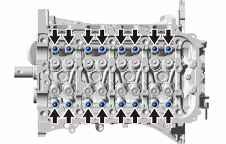
Remove the 16 valve lash adjuster assemblies from the cylinder head sub-assembly.
Tech Tips
Arrange the removed parts in the correct order.
-
-
REMOVE CAMSHAFT HOUSING SUB-ASSEMBLY
-
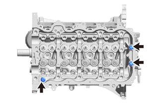
Remove the 3 bolts.
-
*a Protective Tape Using a screwdriver with its tip wrapped with protective tape, remove the camshaft housing sub-assembly by prying between the cylinder head sub-assembly and camshaft housing sub-assembly.
Note
Be careful not to damage the contact surfaces of the cylinder head sub-assembly and camshaft housing sub-assembly.
-
-
REMOVE STUD BOLT
Note
If a stud bolt is deformed or its threads are damaged, replace it.
-
*a Camshaft Housing Sub-assembly Upper Side Using an E8 "TORX" socket wrench, remove the stud bolt from the camshaft housing sub-assembly.
-
Using an E8 "TORX" socket wrench, remove the stud bolt from the timing chain cover assembly.
-
-
REMOVE CYLINDER HEAD SUB-ASSEMBLY
-
REMOVE CYLINDER HEAD GASKET
-
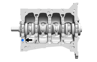
REMOVE CYLINDER BLOCK WATER JACKET SPACER
-
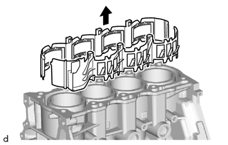
Remove the 2 cylinder block water jacket spacers from the cylinder block sub-assembly.
-
-
REMOVE OIL PAN DRAIN PLUG
-
Remove the oil pan drain plug and oil pan drain plug gasket from the oil pan sub-assembly.
-
-
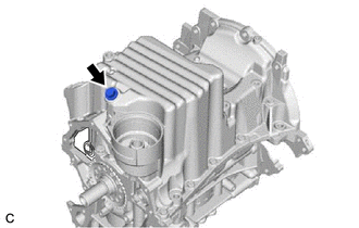
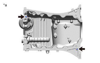
REMOVE OIL PAN SUB-ASSEMBLY
-
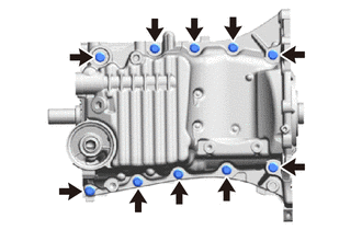
Remove the 10 bolts from the oil pan sub-assembly.
-
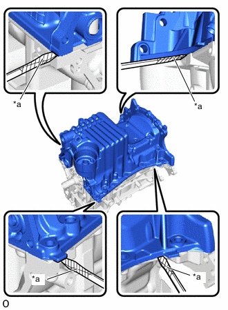
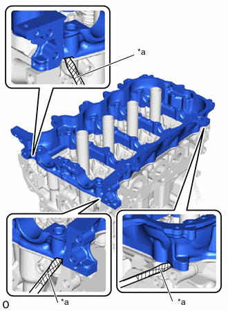
*a Protective Tape Using a screwdriver with its tip wrapped with protective tape, remove the oil pan sub-assembly by prying between the oil pan sub-assembly and cylinder block sub-assembly.
Note
Be careful not to damage the contact surfaces of the cylinder block sub-assembly and oil pan sub-assembly.
-
Remove the No. 1 oil pan gasket from the cylinder block sub-assembly.
-
-
REMOVE NO. 2 OIL PAN BAFFLE PLATE
-
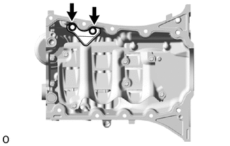
Remove the 2 bolts and No. 2 oil pan baffle plate from the oil pan sub-assembly.
-
-
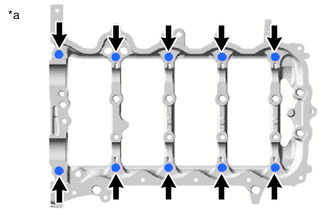
REMOVE NO. 1 OIL PAN BAFFLE PLATE
-
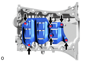
Remove the 6 bolts and No. 1 oil pan baffle plate from the oil pan sub-assembly.
-
-
REMOVE OIL STRAINER SUB-ASSEMBLY
-
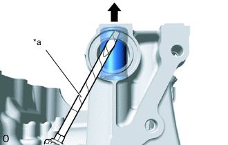
*a Protective Tape Using a screwdriver with its tip wrapped with protective tape, push the oil strainer sub-assembly as shown in the illustration.
Note
Be careful not to damage the contact surfaces of the oil pan sub-assembly.
-
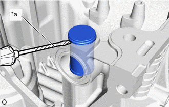
*a Protective Tape Using a screwdriver with its tip wrapped with protective tape, remove the oil strainer sub-assembly to the oil pan sub-assembly as shown in the illustration.
Note
Be careful not to damage the contact surfaces of the oil pan sub-assembly.
-
Remove the oil strainer O-ring from the oil strainer sub-assembly.
-
-
REMOVE STRAIGHT PIN
Note
It is not necessary to remove the straight pins unless they are being replaced.
-
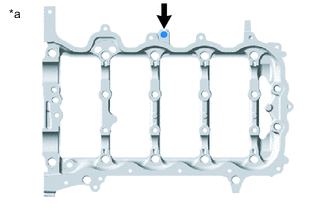
*a Oil Pan Sub-assembly Upper Side Remove the 2 straight pins from the oil pan sub-assembly.
-
-
REMOVE RING PIN
Note
It is not necessary to remove the ring pins unless they are being replaced.
-
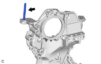
*a Camshaft Housing Sub-assembly Upper Side Remove the 10 ring pins from the camshaft housing sub-assembly.
-