ENGINE ASSEMBLY INSTALLATION

CAUTION / NOTICE / HINT
PROCEDURE
-
INSTALL ENGINE MOUNTING INSULATOR LH
Tech Tips
Perform this procedure only when replacement of the engine mounting insulator LH is necessary.
-
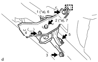
*a Temporarily Tighten Engage the hook and temporarily install the engine mounting insulator LH to the vehicle.
-
Install the 5 bolts in the order shown in the illustration.
- Torque:
- 52 N*m { 530 kgf*cm, 38 ft.*lbf }
-
-
INSTALL ENGINE MOUNTING INSULATOR SUB-ASSEMBLY RH
Tech Tips
Perform this procedure only when replacement of the engine mounting insulator sub-assembly RH is necessary.
-
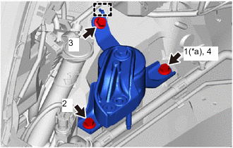
*a Temporarily Tighten Engage the hook and temporarily install the engine mounting insulator sub-assembly RH to the vehicle.
-
Install the 3 bolts in the order shown in the illustration.
- Torque:
- 52 N*m { 530 kgf*cm, 38 ft.*lbf }
-
-
INSTALL ENGINE HANGER
-
REMOVE ENGINE STAND
-
Using an engine sling device and chain block, secure the engine assembly.
Note
-
Pay attention to the angle of the engine sling device as the engine assembly or engine hanger may be damaged or deformed if the angle is incorrect.
-
Do not perform any procedure while the engine assembly is suspended because doing so may cause the engine assembly to drop, resulting in injury. However, the engine assembly needs to be suspended when it is installed to or removed from an engine stand.
-
-
Remove the engine assembly from the engine stand.
-
-
INSTALL DRIVE PLATE AND RING GEAR SUB-ASSEMBLY (for CVT)
-
INSTALL FLYWHEEL SUB-ASSEMBLY (for Manual Transaxle)
-
INSTALL CONTINUOUSLY VARIABLE TRANSAXLE ASSEMBLY (for CVT)
-
INSTALL CLUTCH DISC ASSEMBLY (for Manual Transaxle)
-
INSTALL MANUAL TRANSAXLE ASSEMBLY (for Manual Transaxle)
-
CONNECT WATER INLET HOSE (for CVT)
-
Connect the water inlet hose to the No. 2 water by-pass pipe and slide the hose clip to secure it.
-
-
INSTALL DRIVE PLATE AND TORQUE CONVERTER ASSEMBLY SETTING BOLT (for CVT)
-
INSTALL FLYWHEEL HOUSING SIDE COVER
-
Install the flywheel housing side cover to the cylinder block sub-assembly.
-
-
INSTALL STARTER ASSEMBLY
-
INSTALL ENGINE WIRE
-
Connect all of the connectors and wire harness clamps, and install the engine wire to the engine assembly.
-
Connect the engine wire to the cylinder head cover sub-assembly with the 2 nuts.
- Torque:
- 8.4 N*m { 86 kgf*cm, 74 in.*lbf }
-
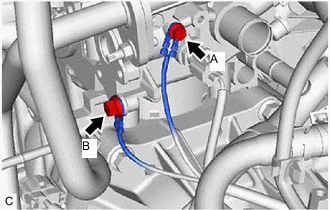
Connect the engine wire to the cylinder head sub-assembly with the 2 bolts.
- Torque:
- Bolt A
- 8.4 N*m { 86 kgf*cm, 74 in.*lbf }
- Bolt B
- 12.8 N*m { 131 kgf*cm, 9 ft.*lbf }
-
Connect the engine wire to the transaxle assembly with the bolt.
- Torque:
- 12.8 N*m { 131 kgf*cm, 9 ft.*lbf }
-
-
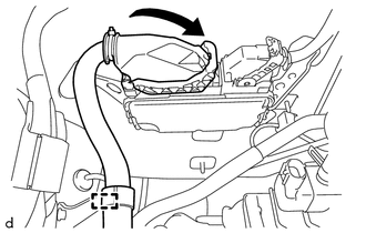
CONNECT VENTILATION HOSE ASSEMBLY
-
Connect the ventilation hose assembly to the heater water pipe and slide the hose clip to secure it.
-
-
CONNECT INLET HEATER WATER HOSE A (for CVT)
-
Connect the inlet heater water hose A to the cylinder head sub-assembly and exhaust cooler assembly and slide the 2 hose clips to secure them.
-
Engage the 2 clamps.
-
-
CONNECT INLET HEATER WATER HOSE A (for Manual Transaxle)
-
Connect the inlet heater water hose A to the cylinder head sub-assembly and exhaust cooler assembly and slide the 2 hose clips to secure them.
-
Engage the clamp.
-
-
INSTALL ENGINE WITH TRANSAXLE ASSEMBLY
-
Set the engine with transaxle assembly and front suspension crossmember sub-assembly on an engine lifter.
Note
-
Keep the engine with transaxle assembly and front crossmember sub-assembly horizontal.
-
As the engine with transaxle assembly is very heavy, be sure to support it securely.
-
-
Remove the 2 bolts, No. 1 engine hanger and No. 2 engine hanger from the cylinder head sub-assembly.
-
Operate the engine lifter and connect the engine mounting insulator sub-assembly RH to the timing chain cover assembly with the bolt and 2 nuts.
- Torque:
- 52 N*m { 530 kgf*cm, 38 ft.*lbf }
Note
Make sure that the engine is clear of all wiring and hoses.
-
Operate the engine lifter and connect the engine mounting insulator LH to the engine mounting bracket LH with the through bolt and nut.
- Torque:
- 52 N*m { 530 kgf*cm, 38 ft.*lbf }
Note
Make sure that the engine is clear of all wiring and hoses.
Tech Tips
Tighten by holding the nut and turning the through bolt.
-
Temporarily install the front suspension crossmember sub-assembly to the vehicle with the 6 bolts.
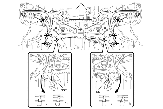
*a Correct *b Incorrect 
Front Side of Vehicle - - -
By inserting SST into the datum holes in the front suspension crossmember sub-assembly RH and LH alternately, tighten bolts A, B and C on both sides to the specified torque, in several steps.
- SST
- 09670-00011
- Torque:
- Bolt A
- 87 N*m { 887 kgf*cm, 64 ft.*lbf }
- Bolt B
- 151 N*m { 1540 kgf*cm, 111 ft.*lbf }
- Bolt C
- 98 N*m { 999 kgf*cm, 72 ft.*lbf }
Note
Insert SST into the datum hole vertically.
-
-
INSTALL WIRE HARNESS CLAMP BRACKET
-
Install the wire harness clamp bracket to the transaxle assembly with the bolt.
- Torque:
- 63 N*m { 642 kgf*cm, 46 ft.*lbf }
-
Engage the 2 clamps and connect the engine wire to the wire harness clamp bracket.
-
-
INSTALL NO. 1 STEERING COLUMN HOLE COVER SUB-ASSEMBLY
-
INSTALL STEERING SLIDING YOKE SUB-ASSEMBLY
-
INSTALL COLUMN HOLE COVER SILENCER SHEET
-
CONNECT ENGINE WIRE (for LHD)
-
Engage the clamp to connect the engine wire to the battery current sensor holder.
-
Connect the battery state sensor assembly connector.
-
Connect the 2 connectors of the positive (+) battery terminal.
-
Engage the 2 claws to connect the engine wire to the engine room relay block.
-
Connect the 2 connectors to the engine room relay block.
-
Engage the clamp to connect the engine wire to the vehicle.
-
Connect the engine wire to the vehicle with the bolt.
- Torque:
- 8.4 N*m { 86 kgf*cm, 74 in.*lbf }
-
Install the relay block cover to the engine room relay block.
-
Connect the ECM connector and lock with the lever.
Note
-
When connecting connectors, make sure that foreign substances such as mud or water droplets do not adhere to them.
-
Securely lock with the lever.
-
-
Engage the clamp.
-
Engage the clamp to connect the engine wire to the air cleaner bracket.
-
-
CONNECT ENGINE WIRE (for RHD)
-
Engage the clamp to connect the engine wire to the battery current sensor holder.
-
Connect the battery state sensor assembly connector.
-
Connect the 2 connectors of the positive (+) battery terminal.
-
Engage the 2 claws to connect the engine wire to the engine room relay block.
-
Connect the 2 connectors to the engine room relay block.
-
Engage the clamp to connect the engine wire to the vehicle.
-
Connect the engine wire to the vehicle with the bolt.
- Torque:
- 8.4 N*m { 86 kgf*cm, 74 in.*lbf }
-
Install the relay block cover to the engine room relay block.
-
Connect the ECM connector and lock with the lever.
Note
-
When connecting connectors, make sure that foreign substances such as mud or water droplets do not adhere to them.
-
Securely lock with the lever.
-
-
Engage the clamp to connect the engine wire to the air cleaner bracket.
-
-
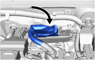
INSTALL COMPRESSOR WITH PULLEY ASSEMBLY (w/ Air Conditioning System)
-
Using an E8 "TORX" socket wrench, install the compressor with pulley assembly to the cylinder block sub-assembly and oil pan sub-assembly with the stud bolt.
- Torque:
- 9.8 N*m { 100 kgf*cm, 87 in.*lbf }
-
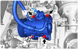

Bolt Nut Temporarily install the compressor with pulley assembly to the cylinder block sub-assembly and oil pan sub-assembly with the 3 bolts and nut.
-
Fully tighten the 3 bolts and nut in the order shown in the illustration.
- Torque:
- 24.5 N*m { 250 kgf*cm, 18 ft.*lbf }
-
-
INSTALL CLUTCH HOSE (for Manual Transaxle)
-
CONNECT TRANSMISSION CONTROL CABLE ASSEMBLY (for CVT)
-
CONNECT TRANSMISSION CONTROL CABLE ASSEMBLY (for Manual Transaxle)
-
CONNECT FUEL TUBE SUB-ASSEMBLY
-
INSTALL NO. 2 EFI FUEL PIPE CLAMP
-
CONNECT INLET HEATER WATER HOSE A
-
Connect the inlet heater water hose A to the heater radiator assembly and slide the hose clip to secure it.
Note
Do not apply excessive force to the inlet heater water hose A.
-
-
CONNECT OUTLET HEATER WATER HOSE A
-
Connect the outlet heater water hose A to the heater radiator assembly and slide the hose clip to secure it.
Note
Do not apply excessive force to the outlet heater water hose A.
-
-
CONNECT NO. 2 RADIATOR HOSE
-
Connect the No. 2 radiator hose to the water inlet with thermostat sub-assembly and slide the hose clip to secure it.
-
-
CONNECT NO. 1 RADIATOR HOSE
-
Connect the No. 1 radiator hose to the cylinder head sub-assembly and slide the hose clip to secure it.
-
-
INSTALL GENERATOR ASSEMBLY
-
for DENSO Made:
-
for VALEO Made:
-
-
INSTALL NO. 1 EXHAUST MANIFOLD HEAT INSULATOR
-
INSTALL OIL LEVEL DIPSTICK GUIDE O-RING
-
INSTALL OIL LEVEL DIPSTICK GUIDE
-
INSTALL OIL LEVEL DIPSTICK SUB-ASSEMBLY
-
INSTALL FAN AND GENERATOR V BELT
-
CONNECT UNION TO CONNECTOR TUBE HOSE
-
CONNECT FUEL VAPOR FEED HOSE ASSEMBLY
-
Engage the clamp to connect the hose clamp to the No. 3 water by-pass hose.
-
Connect the fuel vapor feed hose assembly to the purge valve (purge VSV) and slide the hose clip to secure it.
-
-
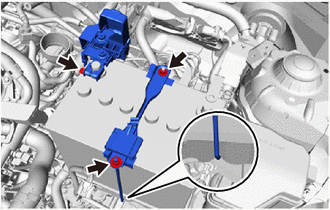
INSTALL BATTERY CARRIER
-
Install the battery carrier to the vehicle with the 5 bolts.
- Torque:
- 17.2 N*m { 175 kgf*cm, 13 ft.*lbf }
-
Engage the 4 clamps to connect the engine wire to the battery carrier.
-
-
INSTALL BATTERY TRAY
-
Install the battery tray to the battery carrier.
-
-
INSTALL BATTERY
-
Install the battery to the battery tray.
-
Install the battery clamp sub-assembly to the battery carrier with the 2 nuts and battery clamp bolt.
- Torque:
- 3.5 N*m { 36 kgf*cm, 31 in.*lbf }
Tech Tips
Engage the hook of the battery clamp bolt to the notch of the battery carrier.
-
Connect the cable to the positive (+) battery terminal and tighten the nut.
- Torque:
- 5.4 N*m { 55 kgf*cm, 48 in.*lbf }
-
Close the fusible link cover.
-
-
INSTALL AIR CLEANER CASE SUB-ASSEMBLY
-
Install the air cleaner case sub-assembly to the air cleaner bracket with the 2 bolts.
- Torque:
- 7.8 N*m { 80 kgf*cm, 69 in.*lbf }
-
Engage the clamp to connect the engine wire to the air cleaner case sub-assembly.
-
-
INSTALL AIR CLEANER FILTER ELEMENT SUB-ASSEMBLY
-
Install the air cleaner filter element sub-assembly to the air cleaner case sub-assembly.
-
-
INSTALL AIR CLEANER CAP SUB-ASSEMBLY
-
Engage the 2 guides to install the air cleaner cap sub-assembly to the air cleaner case sub-assembly.
-
Engage the 2 clamps of the air cleaner cap sub-assembly.
-
Engage the 2 clamps to connect the engine wire to the air cleaner cap sub-assembly.
-
Connect the mass air flow meter connector.
-
-
INSTALL AIR CLEANER HOSE ASSEMBLY
-
CONNECT NO. 1 AIR HOSE (for CVT)
-
CONNECT NO. 2 VACUUM SWITCHING VALVE ASSEMBLY (for CVT)
-
CONNECT NO. 2 VENTILATION HOSE
-
INSTALL OUTER COWL TOP PANEL
-
for LHD:
-
for RHD:
-
-
INSTALL INNER COWL TOP TO COWL BRACE
-
for LHD:
-
for RHD:
-
-
INSTALL FRONT NO. 1 VENTILATOR SEAL
-
for LHD:
-
for RHD:
-
-
INSTALL FRONT AIR SHUTTER SEAL RH
-
for LHD:
-
for RHD:
-
-
INSTALL WINDSHIELD WIPER MOTOR AND LINK
-
INSTALL FRONT DRIVE SHAFT ASSEMBLY
-
INSTALL FRONT EXHAUST PIPE ASSEMBLY
-
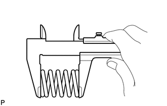
Using a vernier caliper, measure the free length of the compression springs.
Free Length of Compression Spring Compression Spring Standard Free Length Minimum Free Length Front Side 43 mm (1.69 in.) 41.5 mm (1.63 in.) Rear Side 40 mm (1.57 in.) 38.5 mm (1.52 in.) If the free length is less than the minimum, replace the compression spring.
-
Insert a new exhaust pipe gasket to the exhaust manifold converter sub-assembly as far as possible by hand.
-

*1 Exhaust Pipe Gasket *2 Exhaust Manifold Converter Sub-assembly *a Wooden Block *b Plastic Hammer Using a plastic hammer and a wooden block, tap in the exhaust pipe gasket until its surface is flush with the exhaust manifold converter sub-assembly.
Note
-
Install the exhaust pipe gasket in the correct direction.
-
Do not reuse the exhaust pipe gasket.
-
Do not damage the exhaust pipe gasket by dropping it, etc.
-
Do not damage the outer surface of the exhaust pipe gasket.
-
Do not push in the exhaust pipe gasket with the front exhaust pipe assembly when connecting it.
-
-
Insert a new exhaust pipe gasket to the front exhaust pipe assembly as far as possible by hand.
-
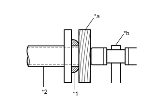
*1 Exhaust Pipe Gasket *2 Front Exhaust Pipe Assembly *a Wooden Block *b Plastic Hammer Using a plastic hammer and a wooden block, tap in the exhaust pipe gasket until its surface is flush with the front exhaust pipe assembly.
Note
-
Install the exhaust pipe gasket in the correct direction.
-
Do not reuse the exhaust pipe gasket.
-
Do not damage the exhaust pipe gasket by dropping it, etc.
-
Do not damage the outer surface of the exhaust pipe gasket.
-
Do not push in the exhaust pipe gasket with the tail exhaust pipe assembly when connecting it.
-
-
Connect the 3 exhaust pipe supports to install the front exhaust pipe assembly to the vehicle.
-
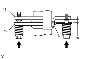
*1 Exhaust Manifold Converter Sub-assembly *2 Front Exhaust Pipe Assembly *3 Exhaust Pipe Gasket *a Space between flanges: 8.5 mm (0.335 in.) Connect the front exhaust pipe assembly to the exhaust manifold converter sub-assembly with the 2 compression springs and 2 bolts.
- Torque:
- 43 N*m { 438 kgf*cm, 32 ft.*lbf }
Tech Tips
After the installation, check that the gaps between the flanges of the front exhaust pipe assembly and exhaust manifold converter sub-assembly are consistent front-to-rear and left-to-right.
-
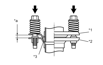
*1 Front Exhaust Pipe Assembly *2 Tail Exhaust Pipe Assembly *3 Exhaust Pipe Gasket *a Space between flanges: 6.5 mm (0.256 in.) Connect the front exhaust pipe assembly to the tail exhaust pipe assembly with the 2 compression springs and 2 bolts.
- Torque:
- 43 N*m { 438 kgf*cm, 32 ft.*lbf }
Tech Tips
After the installation, check that the gaps between the flanges of the front exhaust pipe assembly and tail exhaust pipe assembly are consistent front-to-rear and left-to-right.
-
Engage the clamp to connect the heated oxygen sensor wire to the wire harness clamp bracket.
-
Connect the heated oxygen sensor connector.
-
-
INSTALL FRONT FLOOR CENTER BRACE
-
INSTALL FRONT WHEELS
- Torque:
- 103 N*m { 1050 kgf*cm, 76 ft.*lbf }
-
CONNECT CABLE TO NEGATIVE BATTERY TERMINAL
- Torque:
- 5.4 N*m { 55 kgf*cm, 48 in.*lbf }
Note
When disconnecting the cable, some systems need to be initialized after the cable is reconnected.
-
ADD ENGINE OIL
-
ADD ENGINE COOLANT
-
ADD CONTINUOUSLY VARIABLE TRANSAXLE FLUID (for CVT)
-
ADD MANUAL TRANSAXLE OIL (for Manual Transaxle)
-
CHECK ENGINE OIL LEVEL
-
INSPECT SHIFT LEVER POSITION (for CVT)
-
ADJUST SHIFT LEVER POSITION (for CVT)
-
ADJUST TRANSMISSION CONTROL CABLE ASSEMBLY (for Manual Transaxle)
-
INSPECT FOR COOLANT LEAK
-
INSPECT FOR ENGINE OIL LEAK
-
INSPECT FOR CONTINUOUSLY VARIABLE TRANSAXLE FLUID LEAK (for CVT)
-
INSPECT FOR MANUAL TRANSAXLE OIL LEAK (for Manual Transaxle)
-
INSPECT FOR EXHAUST GAS LEAK
-
INSPECT FOR FUEL LEAK
-
INSPECT IGNITION TIMING
-
INSPECT ENGINE IDLE SPEED
-
INSPECT CO/HC
-
CHECK FOR SPEED SENSOR SIGNAL
-
INSPECT AND ADJUST FRONT WHEEL ALIGNMENT
-
INSTALL NO. 1 ENGINE COVER
-
INSTALL ENGINE UNDER COVER RH
-
Install engine under cover RH to the vehicle with the 2 bolts and screw.
- Torque:
- Bolt
- 5.0 N*m { 51 kgf*cm, 44 in.*lbf }
-
-
INSTALL ENGINE UNDER COVER LH
-
Install engine under cover LH to the vehicle with the 3 bolts and 3 screws.
- Torque:
- Bolt
- 5.0 N*m { 51 kgf*cm, 44 in.*lbf }
-