CAUTION / NOTICE / HINT
Perform "Inspection After Repairs" after replacing the engine assembly, cylinder head sub-assembly, camshaft, No. 2 camshaft, camshaft timing gear assembly, camshaft timing exhaust gear assembly, camshaft timing control motor with EDU assembly, fuel injector assembly, engine coolant temperature sensor, spark plug, piston or piston ring.
PROCEDURE
- Click here
INSTALL RING PIN
Note:It is not necessary to remove the ring pins unless they are being replaced.
-
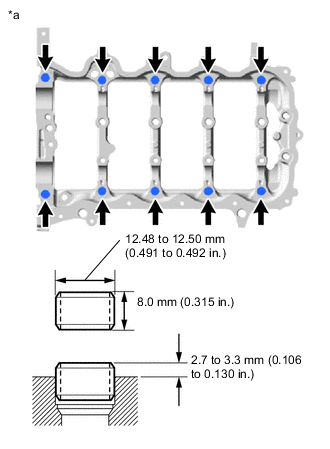
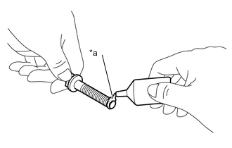
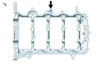
*a Camshaft Housing Sub-assembly Upper Side Using a plastic hammer, tap 10 new ring pins into the camshaft housing sub-assembly.
Standard Protrusion Height 2.7 to 3.3 mm (0.106 to 0.130 in.)
-
- Click here
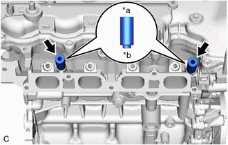
INSTALL STRAIGHT PIN
Note:It is not necessary to remove the straight pins unless they are being replaced.
-
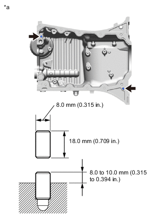
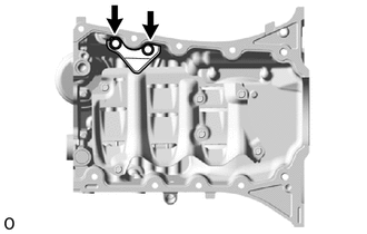
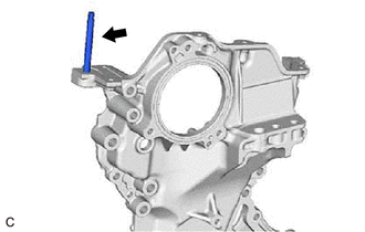
*a Oil Pan Sub-assembly Upper Side Using a plastic hammer, tap 2 new straight pins into the oil pan sub-assembly.
Standard Protrusion Height 8.0 to 10.0 mm (0.315 to 0.394 in)
-
- Click here
INSTALL OIL STRAINER SUB-ASSEMBLY
-
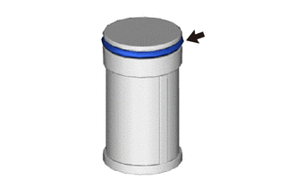
Install the oil strainer O-ring to a new oil strainer sub-assembly.
Note:Do not twist the oil strainer O-ring.
-
Apply a light coat of engine oil to a new oil strainer O-ring.
-
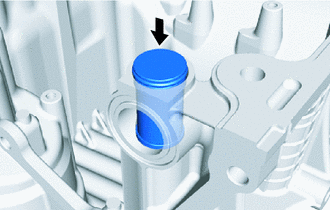
Install the oil strainer sub-assembly to the oil pan sub-assembly.
Note:Do not twist the oil strainer O-ring.
-
- Click here
INSTALL NO. 1 OIL PAN BAFFLE PLATE
-
Temporarily install the No. 1 oil pan baffle plate to the oil pan sub-assembly.
-
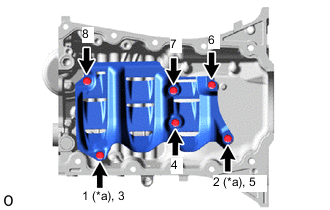
*a Temporarily Tighten Install the 6 bolts in the order shown in the illustration.
10 N*m 102 kgf*cm 7 ft.*lbf
-
- Click here
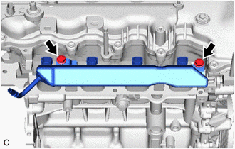
INSTALL NO. 2 OIL PAN BAFFLE PLATE
-
Install the No. 2 oil pan baffle plate to the oil pan sub-assembly with the 2 bolts.
21 N*m 214 kgf*cm 15 ft.*lbf
-
- Click here
INSTALL OIL PAN SUB-ASSEMBLY
-
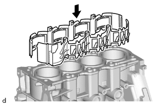
Install a new No. 1 oil pan gasket to the cylinder block sub-assembly.
-
Clean and degrease the oil pan sub-assembly and cylinder block sub-assembly.
-
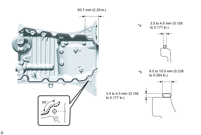
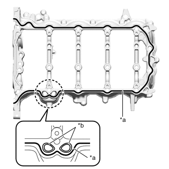
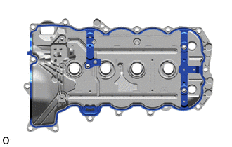
*a Continuous Line Area *b Dashed Line Area Apply seal packing as shown in the illustration.
Seal Packing Toyota Genuine Seal Packing Black, Three Bond 1207B or equivalent Note:
-
Install the oil pan sub-assembly within 3 minutes and tighten the bolts within 15 minutes of applying seal packing.
-
Do not add engine oil for at least 2 hours after installation.
-
Do not start the engine for at least 2 hours after installation.
-
-
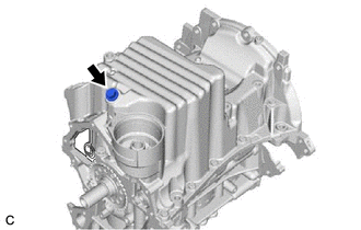
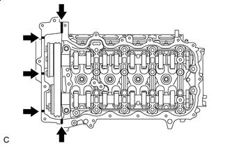
Clean and degrease the bolt (C) and bolt hole.
-
*a Adhesive Apply adhesive to 7.0 mm (0.276 in.) or more of the end of the bolt (C).
Adhesive Toyota Genuine Adhesive 1324, Three Bond 1324 or equivalent Note:To prevent contamination by foreign matter, install immediately after applying adhesive.
-
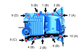
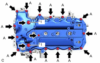
Install the oil pan sub-assembly to the cylinder block sub-assembly with the 10 bolts in the order shown in the illustration.
21 N*m 214 kgf*cm 15 ft.*lbf Bolt Length Item Length (A) 70 mm (2.76 in.) (B), (C) 30 mm (1.18 in.) (D) 55 mm (2.17 in.) -
Wipe off any excess seal packing with a clean piece of cloth.
-
- Click here
INSTALL OIL PAN DRAIN PLUG
-
Install a new oil pan drain plug gasket and oil pan drain plug to the oil pan sub-assembly.
30 N*m 306 kgf*cm 22 ft.*lbf
-
- Click here
INSTALL CYLINDER BLOCK WATER JACKET SPACER
-
Install 2 new cylinder block water jacket spacers to the cylinder block sub-assembly.
-
- Click here
INSTALL CYLINDER HEAD GASKET
- Click here
INSTALL CYLINDER HEAD SUB-ASSEMBLY
- Click here
INSTALL STUD BOLT
Note:If a stud bolt is deformed or its threads are damaged, replace it.
-
*a Camshaft Housing Sub-assembly Upper Side Using an E8 "TORX" socket wrench, install the stud bolt to the camshaft housing sub-assembly.
7.5 N*m 76 kgf*cm 66 in.*lbf -
Using an E8 "TORX" socket wrench, install the stud bolt to the timing chain cover assembly.
7.5 N*m 76 kgf*cm 66 in.*lbf
-
- Click here
INSTALL VALVE LASH ADJUSTER ASSEMBLY
Note:
-
Keep the valve lash adjuster assembly free of dirt and foreign matter.
-
Only use clean engine oil.
-
Place the valve lash adjuster assembly into a container filled with engine oil.
-
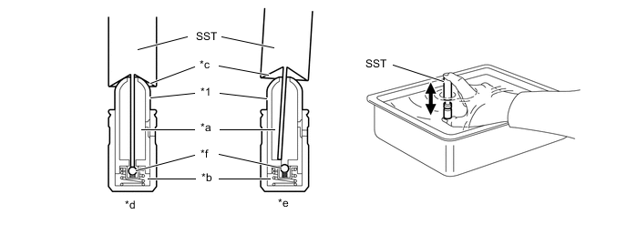
*1 Plunger - - *a Low Pressure Chamber *b High Pressure Chamber *c Taper Part *d Correct *e Incorrect *f Check Ball Insert the tip of SST into the valve lash adjuster assembly plunger and use the tip to press down on the check ball inside the plunger.
09276-75010 -
Squeeze SST and valve lash adjuster assembly together to move the plunger up and down 5 to 6 times.
-
Check the movement of the plunger and bleed it.
OK Plunger moves up and down. Note:When bleeding the high-pressure chamber, make sure that the tip of SST is actually pressing the check ball as shown in the illustration. If the check ball is not pressed, the high-pressure chamber will not be bled.
-
After bleeding, remove SST. Then, try to press the plunger quickly and firmly by hand.
OK Plunger is very difficult to move. Tip:If the plunger moves, bleed air again.
If the plunger moves even after bleeding air 3 times, replace the valve lash adjuster assembly with a new one.
-
Place the valve lash adjuster assembly into a container filled with engine oil, and then bleed air from the low-pressure chamber of the plunger.
-
Apply engine oil to the surface of each valve lash adjuster assembly and the end of each plunger.
-
Install the 16 valve lash adjuster assemblies to the cylinder head sub-assembly by turning clockwise.
Note:Install each valve lash adjuster assembly to the same place it was removed from.
-
- Click here
INSTALL NO. 1 VALVE ROCKER ARM SUB-ASSEMBLY
-
Apply engine oil to the tips of the valve lash adjuster assemblies and valve stem caps.
-
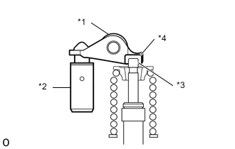
*1 No. 1 Valve Rocker Arm Sub-assembly *2 Valve Lash Adjuster Assembly *3 Valve Stem *4 Valve Stem Cap Install the 16 No. 1 valve rocker arm sub-assemblies as shown in the illustration.
Note:Install each No. 1 valve rocker arm sub-assembly to the same place it was removed from.
-
- Click here
INSTALL CAMSHAFT
-
Clean the camshaft journals.
-
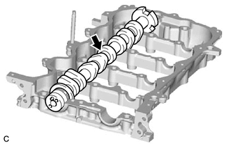
Apply a light coat of engine oil to the camshaft journals.
-
Install the camshaft to the camshaft housing sub-assembly.
-
- Click here
INSTALL NO. 2 CAMSHAFT
-
Clean the No. 2 camshaft journals.
-
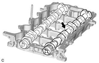
Apply a light coat of engine oil to the No. 2 camshaft journals.
-
Install the No. 2 camshaft to the camshaft housing sub-assembly.
-
- Click here
INSTALL OIL CONTROL VALVE FILTER
-
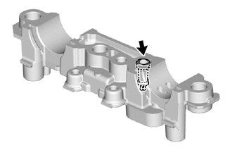
Install the oil control valve filter to the camshaft bearing cap.
-
- Click here
INSTALL CAMSHAFT BEARING CAP
-
Apply engine oil to the camshaft bearing caps.
-
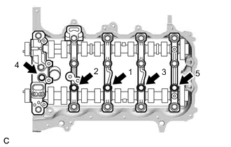
Temporarily install the 5 camshaft bearing caps to the camshaft housing sub-assembly.
-
Tighten the 5 bolts in the order shown in the illustration.
16 N*m 163 kgf*cm 12 ft.*lbf
-
- Click here
INSTALL CAMSHAFT HOUSING SUB-ASSEMBLY
-
Apply engine oil to the cam lobes of the camshaft and roller of each No. 1 valve rocker arm sub-assembly.
-
Clean and degrease the camshaft housing sub-assembly and cylinder head sub-assembly.
-
*a Seal Packing *b Oil Line Apply seal packing in a continuous line as shown in the illustration.
Seal Packing Toyota Genuine Seal Packing Black, Three Bond 1207B or equivalent Seal Packing Diameter 3.5 to 4.0 mm (0.138 to 0.157 in.) Note:
-
Prevent Seal Packing from entering the oil passages.
-
Install the camshaft housing sub-assembly within 3 minutes and tighten the bolts within 15 minutes of applying seal packing.
-
Do not start the engine for at least 2 hours after installation.
-
Do not add engine oil for at least 2 hours after installation.
-
-
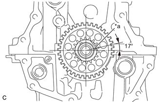
*a Timing Mark Set the crankshaft in the position (40° BTDC) shown in the illustration.
Note:Turn the crankshaft clockwise when positioning the No. 1 cylinder after the camshaft housing sub-assembly is installed.
Tip:Make sure that the timing mark of the crankshaft is positioned as shown in the illustration.
-
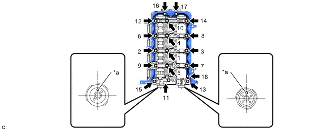
*a Knock Pin - - Set the camshaft and No. 2 camshaft as shown in the illustration.
Tip:Make sure that the knock pin of the camshaft is positioned as shown in the illustration.
-
Set the camshaft housing sub-assembly onto the cylinder head sub-assembly, and uniformly tighten the 18 bolts in the order shown in the illustration.
28 N*m 286 kgf*cm 21 ft.*lbf Note:
-
After installing the camshaft housing sub-assembly, make sure that the knock pin are positioned as shown in the illustration.
-
If any of the bolts are loosened during installation, remove the camshaft housing sub-assembly, clean the installation surfaces, and reapply seal packing.
-
If the camshaft housing sub-assembly is removed because any of the bolts are loosened during installation, make sure that the previously applied seal packing does not enter any oil passages.
-
After installing the camshaft housing sub-assembly, wipe off any seal packing that seeped out from between the camshaft housing sub-assembly and cylinder head sub-assembly.
-
-
- Click here
INSTALL CAMSHAFT TIMING GEAR ASSEMBLY
-
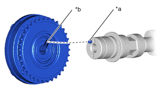
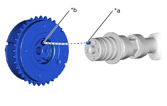
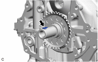
*a Knock Pin *b Knock Pin Hole Check that the knock pin is installed on the camshaft.
-
Put the camshaft timing gear assembly and camshaft together by aligning the knock pin hole and knock pin.
Note:Do not forcibly push in the camshaft timing gear assembly. Otherwise, the seal of the camshaft timing gear assembly may be damaged by the tip of the camshaft knock pin.
-
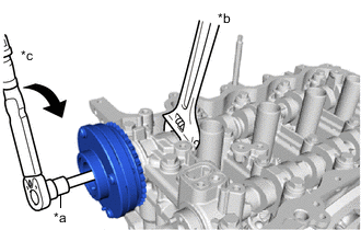
*a 10 mm Bi-hexagon Wrench *b Hold *c Turn Using a wrench, grip the hexagonal portion of the camshaft.
-
Using a 10 mm bi-hexagonal wrench, tighten the bolt to the specified torque.
94 N*m 959 kgf*cm 69 ft.*lbf
-
- Click here
INSTALL CAMSHAFT TIMING EXHAUST GEAR ASSEMBLY
-
*a Knock Pin *b Knock Pin Hole Check that the knock pin is installed on the No. 2 camshaft.
-
Put the camshaft timing exhaust gear assembly and No. 2 camshaft together by aligning the knock pin hole and knock pin.
Note:Do not forcibly push in the camshaft timing exhaust gear assembly. Otherwise, the seal of the camshaft timing exhaust gear assembly may be damaged by the tip of the No. 2 camshaft knock pin.
-
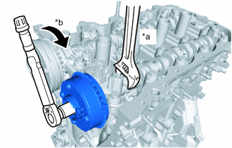
*a Hold *b Turn Using a wrench, grip the hexagonal portion of the No. 2 camshaft.
-
Tighten the bolt to the specified torque.
54 N*m 551 kgf*cm 40 ft.*lbf -
Make sure that the camshaft timing exhaust gear assembly is locked.
-
- Click here
INSTALL CRANKSHAFT TIMING GEAR KEY
-
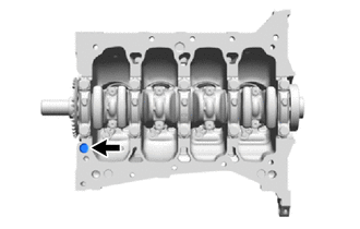
Install the crankshaft timing gear key to the crankshaft.
-
- Click here
INSTALL CRANKSHAFT TIMING SPROCKET
-
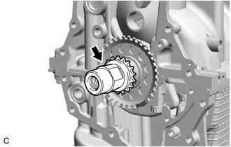
Install the crankshaft timing sprocket to the crankshaft.
-
- Click here
INSTALL TIMING CHAIN GUIDE
-
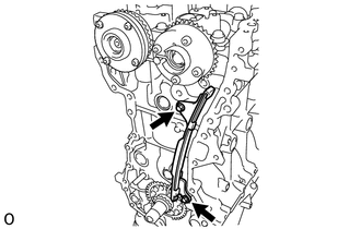
Install the timing chain guide to the cylinder head sub-assembly and cylinder block sub-assembly with the 2 bolts.
10 N*m 102 kgf*cm 7 ft.*lbf
-
- Click here
INSTALL CHAIN SUB-ASSEMBLY
-
*a Timing Mark Set the crankshaft in the position (90° ATDC) as shown in the illustration.
Tip:Make sure that the timing mark of the crankshaft is positioned as shown in the illustration.
-
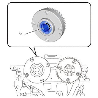
*a Eccentric Shaft Turn the eccentric shaft of the camshaft timing gear assembly clockwise by hand until it stops.
-
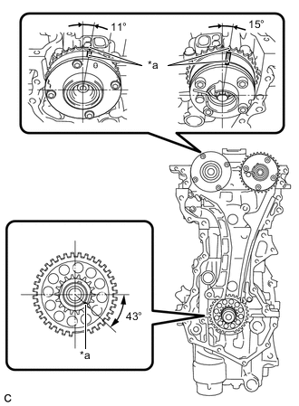
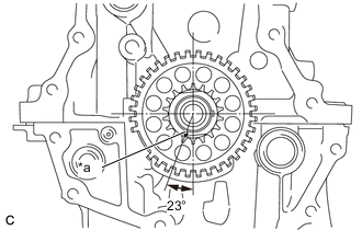
*a Timing Mark Set the camshaft timing gear assembly and camshaft timing exhaust gear assembly in the positions (20° ATDC) shown in the illustration.
-
Set the crankshaft in the position (20°ATDC) shown in the illustration.
Tip:Make sure that the timing mark of the crankshaft is positioned as shown in the illustration.
-
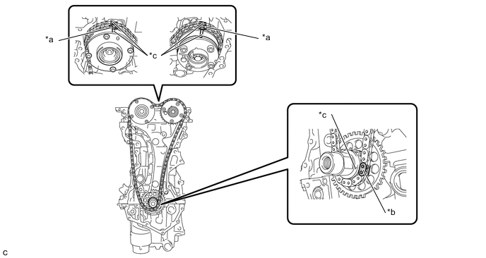
*a Mark Plate (Orange) *b Mark Plate (Yellow) *c Timing Mark - - Align the timing marks of the camshafts with the mark plates (orange) of the chain sub-assembly and install the chain sub-assembly.
Tip:
-
Install the chain sub-assembly so that the mark plates face toward you.
-
The color of the mark plates for the camshaft is orange.
-
-
Align the timing mark of the crankshaft with the mark plate (yellow) of the chain sub-assembly and install the chain sub-assembly.
Tip:The color of the mark plates for the crankshaft is yellow.
-
- Click here
INSTALL TIMING CHAIN TENSION ARM
-
Install the timing chain tension arm to the cylinder block sub-assembly.
-
- Click here
INSTALL NO. 1 CHAIN TENSIONER ASSEMBLY
-
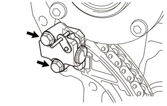
Install a new chain tensioner gasket and No. 1 chain tensioner assembly to the cylinder head sub-assembly with the 2 bolts.
10 N*m 102 kgf*cm 7 ft.*lbf -
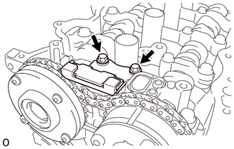
Install the No. 2 chain vibration damper to the camshaft bearing cap with the 2 bolts.
10 N*m 102 kgf*cm 7 ft.*lbf -
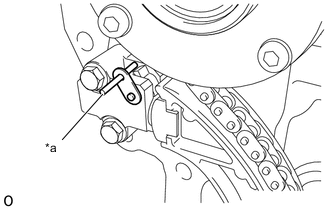
*a Pin Remove the pin of φ3 mm (0.118 in.) diameter from the No. 1 chain tensioner assembly.
-
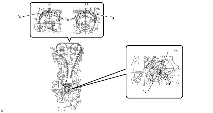
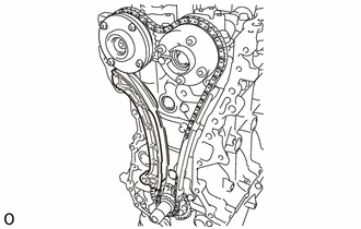
*a Mark Plate (Orange) *b Mark Plate (Yellow) *c Timing Mark *d TDC *e Turn - - Turn the crankshaft approximately 20° counterclockwise to set it to TDC. Make sure that the timing marks and mark plates are correctly positioned and that the chain sub-assembly is securely fitted into the timing chain tension arm, timing chain guide and No. 2 chain vibration damper.
-
- Click here
INSTALL TIMING CHAIN COVER OIL SEAL
- Click here
INSTALL TIMING CHAIN COVER ASSEMBLY
- Click here
INSTALL CRANKSHAFT PULLEY
- Click here
INSTALL REAR ENGINE OIL SEAL
- Click here
INSTALL NO. 2 WATER INLET HOUSING GASKET
-
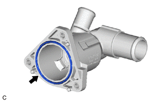
Install a new No. 2 water inlet housing gasket to the water inlet with thermostat sub-assembly.
-
- Click here
INSTALL WATER INLET WITH THERMOSTAT SUB-ASSEMBLY
-
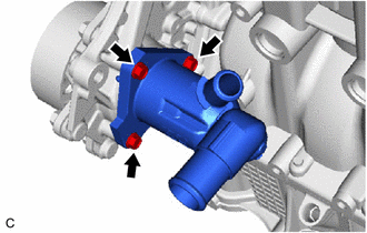
Install the water inlet with thermostat sub-assembly to the timing chain cover assembly with the 3 bolts.
10 N*m 102 kgf*cm 7 ft.*lbf
-
- Click here
INSTALL OIL FILTER CAP ASSEMBLY
- Click here
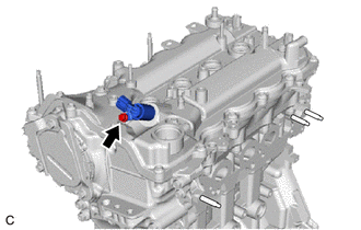
INSTALL ENGINE COOLANT TEMPERATURE SENSOR
-
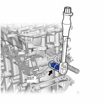
Install a new gasket to the engine coolant temperature sensor.
-
Using SST, install the engine coolant temperature sensor to the cylinder head sub-assembly.
09817-33191 19.6 N*m 200 kgf*cm 14 ft.*lbf Note:If the engine coolant temperature sensor has been struck or dropped, replace it.
-
- Click here
INSTALL KNOCK SENSOR
-
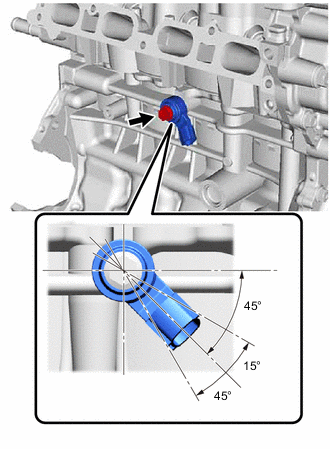
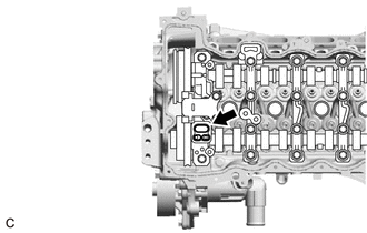
Install the knock sensor to the cylinder block sub-assembly with the bolt as shown in the illustration.
20 N*m 204 kgf*cm 15 ft.*lbf Note:If the knock sensor has been struck or dropped, replace it.
-
- Click here
INSTALL ENGINE OIL PRESSURE SWITCH ASSEMBLY
-
Remove any oil from the threads of the engine oil pressure switch assembly.
-
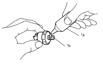
*a Adhesive 1344 *b Oil Inlet Port Apply adhesive to 2 or 3 threads of the engine oil pressure switch assembly.
Adhesive Toyota Genuine Adhesive 1344, Three Bond 1344 or equivalent Note:
-
To prevent contamination by foreign matter, install immediately after applying adhesive.
-
Do not apply adhesive to the oil inlet port of the engine oil pressure switch assembly.
-
-
*a 24 mm Deep Socket Wrench Using a 24 mm deep socket wrench, install the engine oil pressure switch assembly to the cylinder block sub-assembly.
15 N*m 153 kgf*cm 11 ft.*lbf Note:
-
If the engine oil pressure switch assembly has been struck or dropped, replace it.
-
Do not start the engine for at least 1 hour after installation.
-
-
- Click here
INSTALL CRANKSHAFT POSITION SENSOR
-
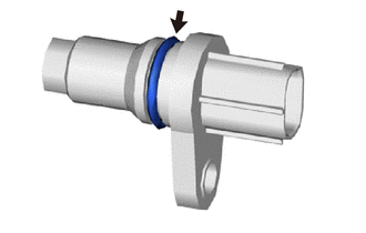
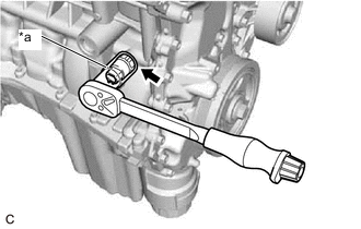
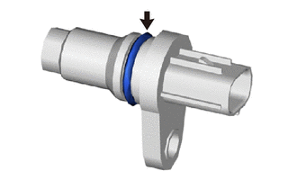
Apply a light coat of engine oil to the O-ring of the crankshaft position sensor.
-
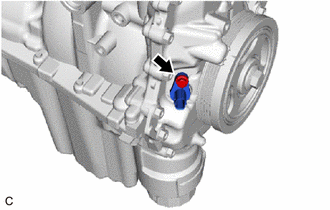
Install the crankshaft position sensor to the timing chain cover assembly with the bolt.
10 N*m 102 kgf*cm 7 ft.*lbf Note:
-
If the crankshaft position sensor has been struck or dropped, replace it.
-
Make sure that the O-ring is not cracked or moved out of place when installing the crankshaft position sensor.
-
-
- Click here
INSTALL CAMSHAFT BEARING CAP OIL HOLE GASKET
-
Install a new camshaft bearing cap oil hole gasket to the camshaft bearing cap.
-
- Click here
INSTALL CYLINDER HEAD COVER GASKET
-
Clean and degrease the cylinder head cover sub-assembly.
-
Install a new cylinder head cover gasket to the cylinder head cover sub-assembly.
-
- Click here
INSTALL CYLINDER HEAD COVER SUB-ASSEMBLY
-
Clean and degrease the cylinder head cover sub-assembly and timing chain cover assembly.
-

Seal Packing Apply seal packing as shown in the illustration.
Seal Packing Toyota Genuine Seal Packing Black, Three Bond 1207B or equivalent Standard Seal Packing Diameter 2.0 mm (0.0787 in.) Note:
-
Install the cylinder head cover sub-assembly within 3 minutes and tighten the bolts within 15 minutes of applying seal packing.
-
Do not add engine oil for at least 2 hours after installation.
-
Do not start the engine for at least 2 hours after installation.
-
-
Clean and degrease the thread of bolt A.
-
*1 Seal Washer and Plate Washer Temporarily install the cylinder head cover sub-assembly with the 18 bolts, 2 plate washers and 2 new seal washers.
Note:Keep bolt A free of oil.
-
Apply a light coat of engine oil to the 2 O-rings of the 2 camshaft position sensors.
-
Temporarily install the camshaft position sensors to the cylinder head cover sub-assembly with the 2 bolts.
Note:
-
If the camshaft position sensor has been struck or dropped, replace it.
-
Make sure that the O-rings are not damaged or moved out of place during installation.
-
-
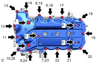
Tighten the 20 bolts in the order shown in the illustration.
10 N*m 102 kgf*cm 7 ft.*lbf
-
- Click here
INSTALL CAMSHAFT TIMING CONTROL MOTOR O-RING
- Click here
INSTALL CAMSHAFT TIMING CONTROL MOTOR WITH EDU ASSEMBLY
- Click here
INSTALL VENTILATION SYSTEM GROMMET
-
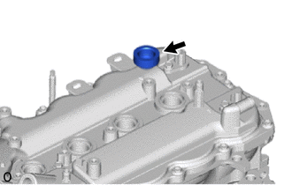
Install the ventilation system grommet to the cylinder head cover sub-assembly.
-
- Click here
INSTALL PCV VALVE (VENTILATION VALVE SUB-ASSEMBLY)
-
Install the pcv valve (ventilation valve sub-assembly) from the ventilation system grommet.
-
- Click here
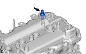
INSTALL CAMSHAFT TIMING OIL CONTROL VALVE O-RING
Tip:This procedure is performed when the camshaft timing oil control valve O-ring must be replaced with a new one.
-
Apply a light coat of engine oil to new camshaft timing oil control valve O-ring, then install it onto the camshaft timing oil control valve assembly.
Note:Do not damage the camshaft timing oil control valve O-ring.
-
- Click here
INSTALL CAMSHAFT TIMING OIL CONTROL VALVE ASSEMBLY
-
Install the camshaft timing oil control valve assembly to the cylinder head cover sub-assembly with the bolt.
10 N*m 102 kgf*cm 7 ft.*lbf Note:
-
If the camshaft timing oil control valve assembly has been struck or dropped, replace it.
-
Make sure that the O-ring is not cracked or moved out of place when installing the camshaft timing oil control valve assembly.
-
-
- Click here
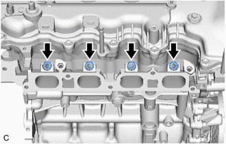
INSTALL SPARK PLUG
-
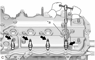
*a 14 mm Spark Plug Wrench Using a 14 mm spark plug wrench, install the 4 spark plugs to the cylinder head sub-assembly.
20 N*m 204 kgf*cm 15 ft.*lbf Note:If the spark plug has been struck or dropped, replace it.
-
- Click here
INSTALL OIL FILLER CAP GASKET
-
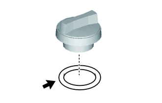
Install the oil filler cap gasket to the oil filler cap assembly.
-
- Click here
INSTALL OIL FILLER CAP ASSEMBLY
-
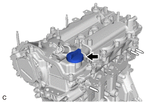
Install the oil filler cap assembly to the cylinder head cover sub-assembly.
-
- Click here
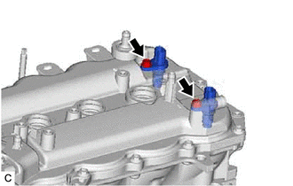
INSTALL FUEL INJECTOR ASSEMBLY
-
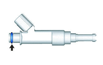
Apply a light coat of gasoline or spindle oil to new O-rings, and then install one to each fuel injector assembly.
Note:Check that there are no scratches or foreign matter in the O-ring groove of the fuel injector assembly.
-
Apply a light coat of gasoline or spindle oil to the contact surfaces of the O-ring of the fuel injector assembly.
-
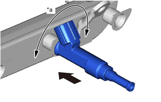
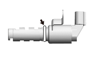
*a Turn Push While turning the fuel injector assembly left and right, install it to the fuel delivery pipe.
Note:
-
Do not damage the fuel injector assembly or O-ring.
-
Make sure that the O-ring is not twisted or moved out of place when installing the fuel injector assembly.
-
After installing each fuel injector assembly, check that it turns smoothly. If not, replace the O-ring with a new one.
-
If the fuel injector assembly has been struck or dropped, replace it.
Tip:Install the other remaining fuel injector assemblies in the same manner.
-
-
- Click here
INSTALL INJECTOR VIBRATION INSULATOR
-
Install 4 new injector vibration insulators to the cylinder head sub-assembly.
-
- Click here
INSTALL NO. 1 DELIVERY PIPE SPACER
-
*a Fuel Delivery Pipe Side *b Cylinder Head Sub-assembly Side Install the 2 No. 1 delivery pipe spacers to the cylinder head sub-assembly.
Note:Install the No. 1 delivery pipe spacers in the correct direction.
-
- Click here
INSTALL FUEL DELIVERY PIPE
-
Install the fuel delivery pipe together with 4 fuel injector assemblies to the cylinder head sub-assembly with the 2 bolts.
28 N*m 286 kgf*cm 21 ft.*lbf Note:
-
Do not drop the fuel injector assembly.
-
Check that the fuel injector assemblies turn smoothly after installing the fuel delivery pipe.
-
If the fuel injector assembly has been struck or dropped, replace it.
Tip:If fuel injector assemblies do not turn smoothly, replace O-rings with new ones, and install them again.
-
-