CYLINDER BLOCK(w/ DPF) INSPECTION

PROCEDURE
-
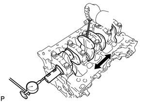
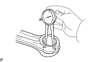
INSPECT CONNECTING ROD THRUST CLEARANCE
-
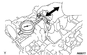
Using a dial indicator, measure the thrust clearance of the connecting rod while moving the connecting rod sub-assembly back and forth.
Standard thrust clearance 0.16 to 0.36 mm (0.0063 to 0.0142 in.) Maximum thrust clearance 0.36 mm (0.0142 in.) If the thrust clearance is greater than the maximum, replace the connecting rod sub-assembly. If necessary, replace the crankshaft.
-
-
INSPECT CONNECTING ROD OIL CLEARANCE
-
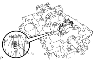
Text in Illustration *a Matchmark Confirm that the matchmarks of the connecting rod and connecting rod cap are aligned.
-
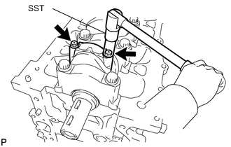
Using SST, remove the 2 bolts and connecting rod cap.
- SST
- 09205-16011
-
Clean the connecting rod bearing and crank pin.
-
Check that the bearing and crank pin are not excessively worn or scratched.
-
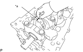
Text in Illustration *a Plastigage Lay a strip of Plastigage across the crank pin.
-
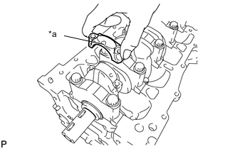
Text in Illustration *a Front Mark Check the front marks of the connecting rod and connecting rod cap, and then install the connecting rod cap onto the connecting rod.
-
Apply a light coat of engine oil to the threads and contact surfaces of the connecting rod bolts.
-
Using SST, temporarily tighten the connecting rod bolts in several steps, and then retighten them to the specified torque.
- SST
- 09205-16011
- Torque:
- 15 N*m { 153 kgf*cm, 11 ft.*lbf }
-
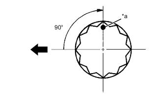
Text in Illustration *a Paint Mark 
Engine Front Mark the front of the connecting rod bolts with paint.
-
Retighten the connecting rod bolts by 90° as shown in the illustration.
Note
Do not turn the crankshaft when measuring.
-
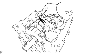
Remove the connecting rod cap, and then measure the Plastigage at its widest point.
Standard oil clearance 0.014 to 0.038 mm (0.0006 to 0.0015 in.) Maximum oil clearance 0.065 mm (0.026 in.) Note
Completely remove the Plastigage.
If the clearance is greater than the maximum, select and install a replacement connecting rod bearing. If necessary, replace the crankshaft.
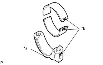
Text in Illustration *a Front Mark *b Number Mark Reference: Number Mark Connecting Rod
External Diameter
mm (in.)
Center Bearing
Thickness
mm (in.)
Oil Clearance
mm (in.)
1 47.000 to 47.008
(1.85039 to 1.85071)
1.489 to 1.493
(0.05862 to 0.05878)
0.014 to 0.038
(0.00055 to 0.00150)
2 47.009 to 47.016
(1.85075 to 1.85102)
1.494 to 1.497
(0.05882 to 0.05894)
↑ 3 47.017 to 47.024
(1.85106 to 1.85134)
1.498 to 1.501
(0.05898 to 0.05909)
↑
-
-
INSPECT CRANKSHAFT THRUST CLEARANCE
-
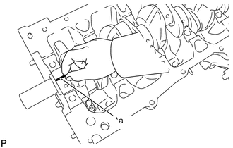
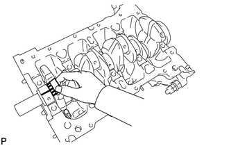
Using a dial indicator, measure the thrust clearance of the crankshaft while moving a screwdriver back and forth between the crankshaft and crankshaft bearing cap.
Standard thrust clearance 0.04 to 0.24 mm (0.0016 to 0.0094 in.) Maximum thrust clearance 0.30 mm (0.0118 in.) If the thrust clearance is greater than the maximum, replace the upper crankshaft thrust washer or crankshaft.
Upper crankshaft thrust washer thickness 2.43 to 2.48 mm (0.0957 to 0.0976 in.)
-
-
INSPECT CYLINDER BLOCK FOR FLATNESS
-
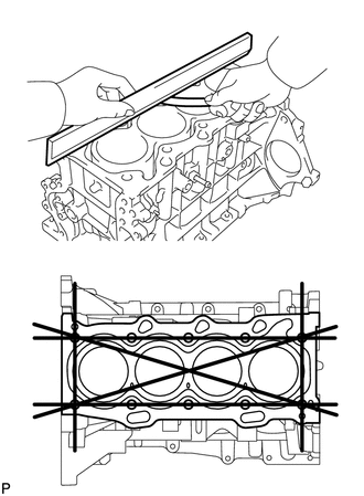
Using a precision straightedge and feeler gauge, measure the warpage of the top surface of the cylinder block sub-assembly.
Maximum warpage 0.05 mm (0.0020 in.)
-
-
INSPECT CYLINDER BORE
-
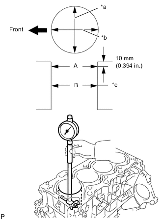
Text in Illustration *a Thrust Direction *b Axial Direction *c Center Engine Front Using a cylinder gauge, measure the cylinder bore diameter at positions A and B in the thrust and axial directions.
Standard diameter 73.000 to 73.013 mm (2.8740 to 2.8745 in.) Maximum diameter 73.133 mm (2.8792 in.) If the average diameter of the 4 positions is greater than the maximum, replace the cylinder block sub-assembly.
-
-
INSPECT PISTON WITH PIN SUB-ASSEMBLY
-
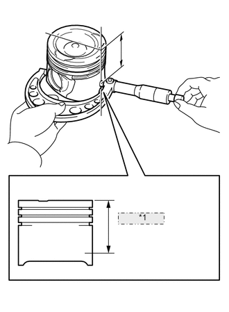
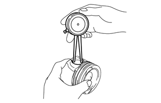
*1 49.9 mm (1.965 in.) Using a micrometer, measure the piston diameter at right angles to the piston pin center line, and at a position 49.9 mm (1.965 in.) from the top of the piston head.
Piston diameter 72.936 to 73.000 mm (2.8715 to 2.8740 in.) If the diameter is not as specified, replace the piston.
-
Using a caliper gauge, measure the internal diameter of the piston pin hole.
Standard Piston Pin Hole Diameter Item Specified Condition
mm (in.)
Mark A 27.019 to 27.023
(1.06374 to 1.06390)
Mark B 27.024 to 27.027
(1.06394 to 1.06405)
Mark C 27.028 to 27.031
(1.06409 to 1.06421)
-
Using a micrometer, measure the external diameter of the piston pin.
Standard Piston Pin Diameter Item Specified Condition
mm (in.)
Mark A 27.008 to 27.012
(1.06331 to 1.06346)
Mark B 27.013 to 27.016
(1.06350 to 1.06362)
Mark C 27.017 to 27.020
(1.06366 to 1.06378)
Note
Do not change the combinations of the pistons and piston pins so that they can be returned to their original locations when reassembling.
-
-
INSPECT PISTON CLEARANCE
-
Subtract the piston diameter measurement from the cylinder bore minimum diameter measurement to calculate the piston clearance.
Standard oil clearance 0 to 0.047 mm (0 to 0.0019 in.) Maximum oil clearance 0.08 mm (0.0032 in.) If the piston clearance is greater than the maximum, replace the piston or cylinder block sub-assembly.
-
Subtract the piston pin diameter measurement from the bushing inside diameter measurement.
Standard oil clearance 0.007 to 0.015 (0.0003 to 0.0006 in.) Maximum oil clearance 0.05 mm (0.0020 in.) If the oil clearance is greater than maximum, replace the bushing. If necessary, replace the piston and piston pin as a set.
-
-
INSPECT RING GROOVE CLEARANCE
-
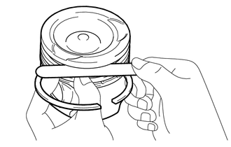
Using a feeler gauge, measure the clearance between the piston ring and ring groove all around the piston.
Standard Ring Groove Clearance Ring Standard
mm (in.)
No. 1 Compression Ring 0.110 to 0.150
(0.0043 to 0.0059)
No. 2 Compression Ring 0.070 to 0.110
(0.0028 to 0.0043)
Oil Ring 0.030 to 0.070
(0.0012 to 0.0028)
If the clearance is not as specified, replace the piston.
-
-
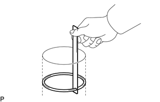
INSPECT PISTON RING END GAP
-
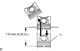
Text in Illustration *1 Piston Ring Using the piston, push the piston ring until it is 110 mm (4.33 in.) from the top of the cylinder block sub-assembly.
-
Using a feeler gauge, measure the end gap.
Standard End Gap Ring Standard
mm (in.)
Maximum
mm (in.)
No. 1 Compression Ring 0.17 to 0.22
(0.0067 to 0.0087)
0.42
(0.0165)
No. 2 Compression Ring 0.65 to 0.75
(0.0256 to 0.0295)
0.80
(0.0315)
Oil Ring 0.10 to 0.30
(0.0039 to 0.0118)
0.70
(0.0276)
If the end gap is greater than the maximum, replace the piston ring set.
-
-
INSPECT CONNECTING ROD SUB-ASSEMBLY
-
Using a caliper gauge, measure the internal diameter of the connecting rod sub-assembly.
Standard Connecting Rod Internal Diameter Item Specified Condition
mm (in.)
Mark A 27.022 to 27.026
(1.06386 to 1.06401)
Mark B 27.027 to 27.030
(1.06405 to 1.06417)
Mark C 27.031 to 27.034
(1.06421 to 1.06433)
If the diameter is greater than the maximum, replace the connecting rod sub-assembly.
-
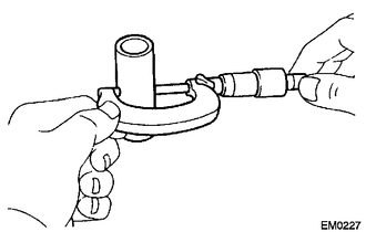
Using a rod aligner and feeler gauge, check the connecting rod alignment.
-
Check the misalignment.
Maximum misalignment 0.05 mm (0.0020 in.) per 100 mm (3.94 in.) If the misalignment is greater than the maximum, replace the connecting rod sub-assembly.
-
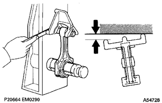
Check the twist.
Maximum twist 0.15 mm (0.006 in.) per 100 mm (3.94 in.) If the twist is greater than the maximum, replace the connecting rod sub-assembly.
-
-
-
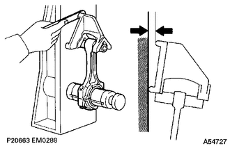
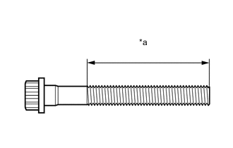
INSPECT CONNECTING ROD BOLT
-
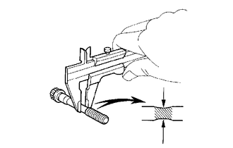
Using a vernier caliper, measure the diameter at the position illustrated.
Standard diameter 6.6 to 6.7 mm (0.260 to 0.264 in.) Minimum diameter 6.4 mm (0.252 in.) If the diameter is less than the minimum, replace the connecting rod bolt.
-
-
INSPECT CRANKSHAFT
-
Inspect the circle runout.
-
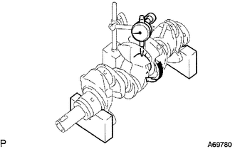
Using a dial indicator and V-blocks, measure the circle runout of the crankshaft.
Maximum circle runout 0.015 mm (0.0006 in.) If the circle runout is greater than the maximum, replace the crankshaft.
-
-
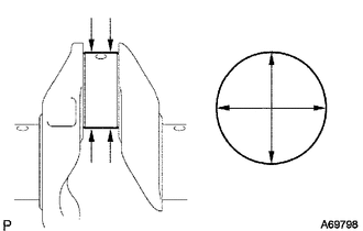
Inspect the diameter.
-
Using a micrometer, measure the diameter of each main journal as illustrated.
Standard diameter 45.988 to 46.000 mm (1.8105 to 1.8110 in.) -
Calculate the taper and out-of-roundness of the main journal.
Maximum taper and out-of-round 0.02 mm (0.0008 in.) If the taper and out-of-roundness are greater than the maximum, replace the crankshaft.
-
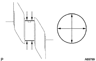
Using a micrometer, measure the diameter of each crank pin as illustrated.
Standard diameter 43.992 to 44.000 mm (1.7320 to 1.7323 in.) -
Calculate the taper and out-of-roundness of the crank pin.
Maximum taper and out-of-round 0.02 mm (0.0008 in.) If the taper and out-of-roundness are greater than the maximum, replace the crankshaft.
-
-
-
INSPECT CRANKSHAFT BEARING CAP SET BOLT
-
Text in Illustration *a Measurement Area Using a vernier caliper, measure the diameter of the crankshaft bearing cap set bolt in the area shown in the illustration.
Standard diameter 10.8 to 11.0 mm (0.425 to 0.433 in.) Minimum diameter 10.6 mm (0.417 in.) If the diameter is less than the minimum, replace the crankshaft bearing cap set bolt.
-
-
INSPECT CRANKSHAFT OIL CLEARANCE
-
Clean the main journal and crankshaft bearing.
-
Install the crankshaft bearing (upper) with the oil groove onto the cylinder block sub-assembly, the crankshaft bearing (lower) onto the crankshaft bearing cap.
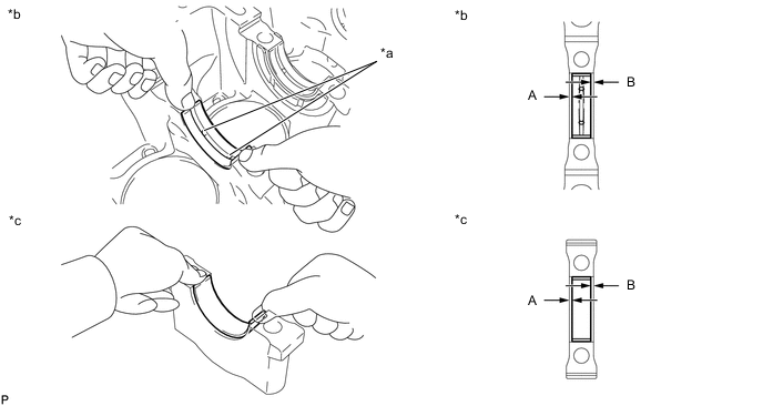
Text in Illustration *a Oil Groove *b Cylinder Block Side *c Crankshaft Bearing Cap Side - - Note
Do not apply engine oil to the contact surface of the cylinder block sub-assembly or the back side of the crankshaft bearing.
Tech Tips
Mass production parts do not have identification marks. If reusing a mass production part, measure the clearance of both sides so that the crankshaft bearing is in the center of the crankshaft bearing cap.
Specified clearance A - B = within 0.8 mm (0.032 in.) -
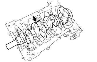
Install the crankshaft onto the cylinder block sub-assembly.
-
Text in Illustration *a Plastigage Lay a strip of Plastigage across the crankshaft journal.
-
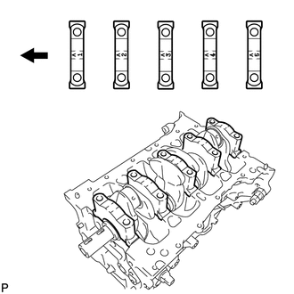
Examine the front marks and imprinted numbers and check that the sequence is as shown in the illustration. Then, install the crankshaft bearing caps onto the cylinder block sub-assembly.
Text in Illustration Engine Front -
Apply a light coat of engine oil to the threads and contact surface of the crankshaft bearing cap set bolt.
-
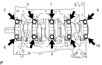
Using several steps, temporarily tighten the crankshaft bearing cap set bolts in the order shown in the illustration, and tighten them to the specified torque (step "g").
- Torque:
- 60 N*m { 612 kgf*cm, 44 ft.*lbf }
-
Text in Illustration *a Paint Mark Engine Front Mark the front of the crankshaft bearing cap set bolts with paint.
-
Retighten the crankshaft bearing cap set bolts by 90° in the same order as step "g".
-
Check that each paint mark is now at a 90° angle from the front.
Note
Do not turn the crankshaft when measuring.
-
Remove the crankshaft bearing cap, and then measure the Plastigage at its widest point.
Standard oil clearance 0.010 to 0.023 mm (0.0004 to 0.0009 in.) Maximum oil clearance 0.07 mm (0.0028 in.) Note
Completely remove the Plastigage.
If the clearance is greater than the maximum, select and install a replacement crankshaft bearing.
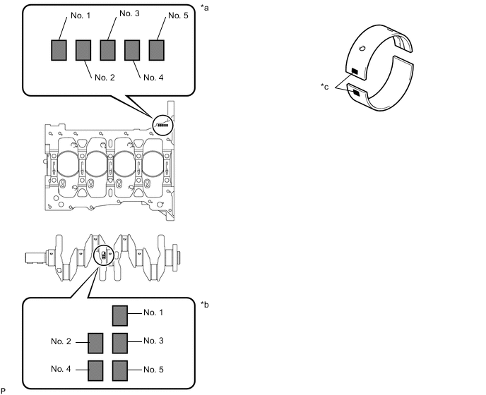
Text in Illustration *a Cylinder Block Number *b Crank Main Journal Number *c Bearing Number - - Tech Tips
-
To select the correct bearing size, calculate the bearing number by adding together the numbers imprinted on the cylinder block sub-assembly and crank main journal.
-
Example:
Imprinted number on the cylinder block is 3.
Imprinted number on the crank main journal is 4.
3 + 4 = 7
Select a bearing with the bearing number 3.
Number Cylinder Block Main Journal Bore Diameter
mm (in.)
Crank Main Journal Diameter
mm (in.)
0 50.000 to 50.002
(1.96850 to 1.96858)
45.999 to 46.000
(1.81098 to 1.81102)
1 50.003 to 50.004
(1.96862 to 1.96866)
45.997 to 45.998
(1.81091 to 1.81094)
2 50.005 to 50.006
(1.96870 to 1.96874)
45.995 to 45.996
(1.81083 to 1.81087)
3 50.007 to 50.009
(1.96878 to 1.96886)
45.993 to 45.994
(1.81075 to 1.81079)
4 50.010 to 50.011
(1.96890 to 1.96894)
45.991 to 45.992
(1.81067 to 1.81071)
5 50.012 to 50.013
(1.96898 to 1.96902)
45.998 to 45.990
(1.81094 to 1.81063)
6 50.014 to 50.016
(1.96906 to 1.96913)
- Cylinder Block
Number + Crank
Main Journal Number
Bearing Number Center Bearing Thickness
mm (in.)
Oil Clearance
mm (in.)
0 to 2 1 1.992 to 1.995
(0.07843 to 0.07854)
0.010 to 0.023
(0.00039 to 0.00091)
3 to 5 2 1.996 to 1.998
(0.07858 to 0.07866)
↑ 6 to 8 3 1.999 to 2.001
(0.07870 to 0.07878)
↑ 9 to 11 4 2.002 to 2.004
(0.07882 to 0.07890)
↑
-
-