CYLINDER BLOCK(w/ DPF) DISASSEMBLY

PROCEDURE
-
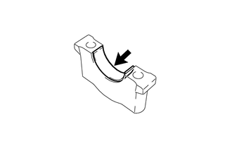
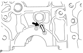
REMOVE TUBE CONNECTOR
-
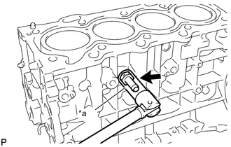
Text in Illustration *a 14 mm Deep Socket Wrench Using a 14 mm deep socket wrench, remove the tube connector from the cylinder block sub-assembly.
-
-
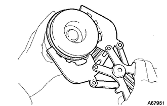
REMOVE PISTON SUB-ASSEMBLY WITH CONNECTING ROD
-
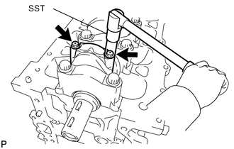
Using SST, remove the connecting rod bolts and connecting rod cap.
- SST
- 09205-16011
-
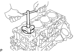
Using a ridge reamer, remove all the carbon from the top of the cylinder.
-
Push the piston, connecting rod and connecting rod bearing (upper) through the top of the cylinder block sub-assembly.
Tech Tips
-
Keep the connecting rod bearing, connecting rod and connecting rod cap together.
-
Keep the pistons and connecting rods in the correct order so that they can be returned to their original locations when reassembling.
-
-
-
REMOVE CONNECTING ROD BEARING
-
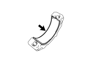
Remove the connecting rod bearing (lower) from the connecting rod cap.
-
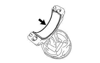
Remove the connecting rod bearing (upper) from the connecting rod.
-
-
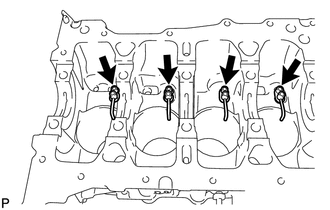
REMOVE CRANKSHAFT
-
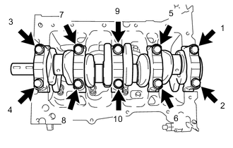
Uniformly loosen the crankshaft bearing cap set bolts in several steps in the order shown in the illustration and remove them.
-
Remove the crankshaft bearing caps and crankshaft.
-
-
REMOVE UPPER CRANKSHAFT THRUST WASHER
-
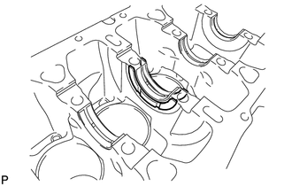
Remove the upper crankshaft thrust washers from the cylinder block sub-assembly.
-
-
REMOVE CRANKSHAFT BEARING
-
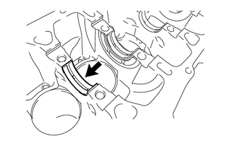
Remove the crankshaft bearing (upper) from the cylinder block sub-assembly.
-
Remove the crankshaft bearing (lower) from the crankshaft bearing cap.
-
-
REMOVE PISTON RING SET
Tech Tips
Keep the piston rings in the correct combination and order so that they can be returned to their original locations when reassembled.
-
Using a piston ring expander, remove the No. 1 compression ring, No. 2 compression ring, oil ring (side rail) and oil ring (expander).
-
-
REMOVE PISTON
-
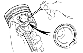
Using a screwdriver, pry out the snap ring and remove the piston pin.
Note
Do not change the combinations of the pistons and piston pins.
-
-
REMOVE NO. 1 OIL NOZZLE SUB-ASSEMBLY
-
Using a 5 mm socket hexagon wrench, remove the 4 bolts and 4 No. 1 oil nozzle sub-assemblies from the cylinder block sub-assembly.
-
-
REMOVE OIL JET
-
Remove the oil jet from the cylinder block sub-assembly.
-