PROCEDURE
- Click here
INSPECT CYLINDER HEAD SUB-ASSEMBLY
-
Inspect the flatness.
-
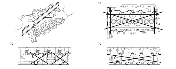
Using a precision straightedge and feeler gauge, measure the warpage on the cylinder block side, intake air connector and exhaust manifold side.
Table 1. Text in Illustration *a Cylinder Block Side *b Exhaust Manifold Side *c Intake Air Connector Side - - Maximum Warpage Surface Specified Condition Cylinder block side 0.08 mm (0.0032 in.) Intake air connector side 0.20 mm (0.0079 in.) Exhaust manifold side 0.20 mm (0.0079 in.) If the warpage is greater than the maximum, replace the cylinder head sub-assembly.
-
-
Inspect for cracks.
-
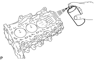
Using a dye penetrant, check the combustion chambers, intake ports, exhaust ports and contact surface of the cylinder block sub-assembly for cracks.
If cracked, replace the cylinder head sub-assembly.
-
-
- Click here
INSPECT VALVE SEAT
-
Apply a light coat of Prussian blue to each valve face.
Table 2. Text in Illustration *a Width -
Gently push the valve seat with the valve installed onto the cylinder head sub-assembly.
Note:Do not rotate the valve.
-
Remove the valve from the cylinder head sub-assembly.
-
If Prussian blue appears 360° around the valve face, the valve is concentric. If not, replace the valve.
-
If Prussian blue appears 360° around the valve seat, the guide and valve face are concentric. If not, resurface the valve seat.
-
Check that the valve seat contact is in the middle of the valve face with the following width.
-
-
- Click here
INSPECT CAMSHAFT OIL CLEARANCE
-
Clean the camshaft journal and camshaft bearing cap.
-
Set the camshaft to the cylinder head sub-assembly.
-
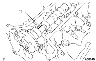
Lay a strip of Plastigage across the camshaft journal.
Table 3. Text in Illustration *1 Plastigage Note:Do not turn the camshaft when measuring.
-
Install the camshaft bearing cap (Click here).
-
Remove the camshaft bearing cap (Click here).
-
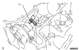
Measure the Plastigage at its widest point.
Table 4. Text in Illustration *1 Plastigage Standard oil clearance 0.037 to 0.073 mm (0.0015 to 0.0029 in.) Maximum oil clearance 0.10 mm (0.0039 in.) Note:Completely remove the Plastigage.
If the clearance is greater than the maximum, replace the cylinder head sub-assembly.
-
- Click here
INSPECT CAMSHAFT THRUST CLEARANCE
-
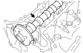
Set the camshaft to the cylinder head sub-assembly, and then install the camshaft bearing cap (Click here).
-
Install the camshaft timing sprocket onto the camshaft (Click here).
-
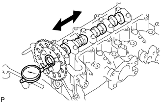
Using a dial indicator, measure the thrust clearance of the camshaft while moving the camshaft back and forth.
Standard thrust clearance 0.080 to 0.180 mm (0.0032 to 0.0071 in.) Maximum thrust clearance 0.25 mm (0.0098 in.) If the thrust clearance is greater than the maximum, replace the cylinder head sub-assembly or camshaft.
-
- Click here
INSPECT INTAKE VALVE
-
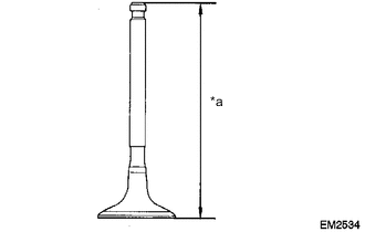
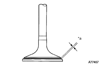
Using a vernier caliper, measure the overall length of the intake valve.
Table 5. Text in Illustration *a Overall Length Standard overall length 99.69 to 100.29 mm (3.9248 to 3.9484 in.) Minimum overall length 99.19 mm (3.9051 in.) If the overall length is less than the minimum, replace the intake valve.
-
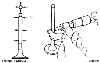
Using a micrometer, measure the diameter of the valve stem.
Table 6. Text in Illustration *a Valve Stem Standard valve stem diameter 5.970 to 5.985 mm (0.2350 to 0.2356 in.) -
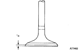
Using a vernier caliper, measure the thickness of the valve head margin.
Table 7. Text in Illustration *a Margin Thickness Standard margin thickness 1.2 mm (0.047 in.) Minimum margin thickness 0.6 mm (0.024 in.) If the margin thickness is less than the minimum, replace the intake valve.
-
- Click here
INSPECT EXHAUST VALVE
-
Using a vernier caliper, measure the overall length of the exhaust valve.
Table 8. Text in Illustration *a Overall Length Standard overall length 99.39 to 99.99 mm (3.9130 to 3.9366 in.) Minimum overall length 98.89 mm (3.8933 in.) If the overall length is less than the minimum, replace the exhaust valve.
-
Using a micrometer, measure the diameter of the valve stem.
Table 9. Text in Illustration *a Valve Stem Standard valve stem diameter 5.965 to 5.980 mm (0.2348 to 0.2354 in.) -
Using a vernier caliper, measure the thickness of the valve head margin.
Table 10. Text in Illustration *a Margin Thickness Standard margin thickness 1.5 mm (0.059 in.) Minimum margin thickness 0.7 mm (0.028 in.) If the overall length is less than the minimum, replace the exhaust valve.
-
- Click here
INSPECT OUTER COMPRESSION SPRING
-
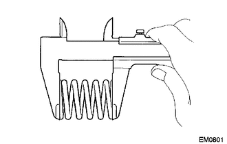
Using a vernier caliper, measure the free length of the outer compression spring.
Standard free length 42.80 mm (1.685 in.) If the free length is not as specified, replace the outer compression spring.
-
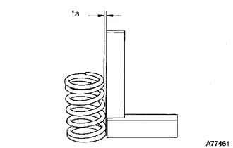
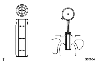
Using steel squares, measure the deviation of the outer compression spring.
Table 11. Text in Illustration *a Deviation Maximum deviation 1.5 mm (0.059 in.) If the deviation is greater than the maximum, replace the outer compression spring.
-
- Click here
INSPECT VALVE GUIDE BUSH OIL CLEARANCE
-
Using a caliper gauge, measure the internal diameter of the valve guide bush.
Standard valve guide bush inside diameter 6.010 to 6.030 mm (0.2366 to 0.2374 in.) -
Subtract the valve stem diameter measurement from the internal diameter measurement of the valve guide bush.
Standard Oil Clearance Valve Guide Bush Specified Condition Intake 0.025 to 0.060 mm (0.0010 to 0.0024 in.) Exhaust 0.030 to 0.065 mm (0.0012 to 0.0026 in.) Maximum Oil Clearance Valve Guide Bush Specified Condition Intake 0.08 mm (0.0031 in.) Exhaust 0.10 mm (0.0039 in.) If the clearance is greater than the maximum, replace the valve and valve guide bush.
-