ENGINE UNIT(w/ DPF) INSTALLATION

PROCEDURE
-
INSTALL NO. 2 OIL PAN COVER SILENCER
-
Install the No. 2 oil pan cover silencer to the oil pan sub-assembly with the 2 bolts and 2 plate washers.
- Torque:
- 7.0 N*m { 71 kgf*cm, 62 in.*lbf }
-
-
INSTALL OIL PAN COVER
-
Install the oil pan cover to the oil pan sub-assembly with the 2 bolts and 2 plate washers.
- Torque:
- 7.0 N*m { 71 kgf*cm, 62 in.*lbf }
-
-
INSTALL NO. 2 TURBOCHARGER STAY
-
Install the No. 2 turbocharger stay to the cylinder head sub-assembly with the 2 bolts.
- Torque:
- 37 N*m { 377 kgf*cm, 27 ft.*lbf }
-
-
INSTALL WIRING HARNESS CLAMP BRACKET
-
Install the wiring harness clamp bracket to the timing chain cover assembly with the bolt.
- Torque:
- 8.4 N*m { 85 kgf*cm, 74 in.*lbf }
-
-
INSTALL V-RIBBED BELT TENSIONER ASSEMBLY
-
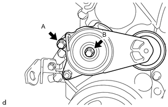
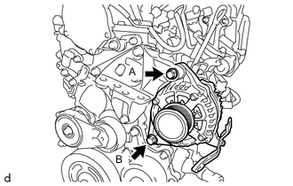
Install the V-ribbed belt tensioner assembly to the timing chain cover assembly with the 2 bolts.
- Torque:
- 24 N*m { 245 kgf*cm, 18 ft.*lbf }
Bolt Length Bolt Length
mm (in.)
A 20 (0.787) B 50 (1.969)
-
-
INSTALL VACUUM PUMP ASSEMBLY
-
Install 2 new O-rings to the vacuum pump assembly.
Note
Do not twist the O-ring.
-
Apply a small amount of engine oil to the 2 O-rings.
-
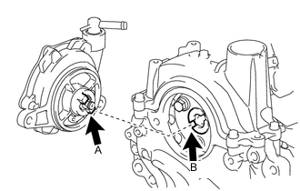
Install the vacuum pump assembly so that the coupling teeth A on the side of the vacuum pump assembly can engage with the tip groove of camshaft B.
-
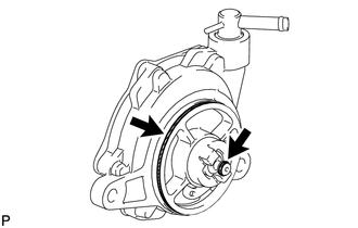
Install the vacuum pump assembly to the cylinder head sub-assembly with the 2 new bolts.
- Torque:
- 21 N*m { 214 kgf*cm, 15 ft.*lbf }
Note
Make sure that the O-ring is not damaged or does not jump out of position during installation.
-
-
INSTALL WATER INLET PIPE
-
Install the water inlet pipe to the cylinder block sub-assembly with the 2 bolts.
- Torque:
- 9.0 N*m { 92 kgf*cm, 80 in.*lbf }
-
-
INSTALL WATER INLET HOSE LH
-
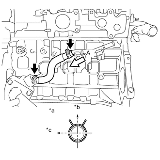
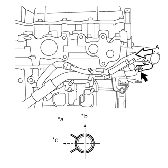
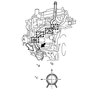
Text in Illustration *a View A *b Upper of Engine *c LH of Engine Install the water inlet hose LH to the water inlet pipe and water inlet housing, and slide the 2 hose clips to secure it.
Note
Perform the installation with the hose clip at the correct angle.
Tech Tips
The hose clip at the water inlet housing can be installed in any orientation, as long as it does not contact any of the surrounding parts.
-
-
INSTALL WATER INLET HOSE RH
-
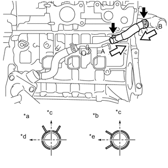
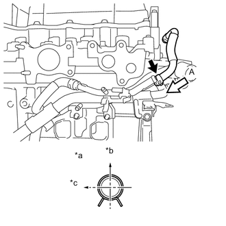
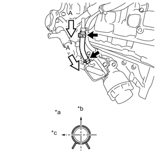
Text in Illustration *a View A *b View B *c Upper of Engine *d RH of Engine *e Rear of Engine Install the water inlet hose RH to the water outlet sub-assembly and water inlet pipe, and slide the 2 hose clips to secure it.
Note
Perform the installation with the hose clip at the correct angle.
-
-
INSTALL WATER BY-PASS PIPE SUB-ASSEMBLY
-
Install a new water by-pass pipe O-ring to the water by-pass pipe sub-assembly.
Note
-
Apply water to all around of the water by-pass pipe O-ring inserting hole surface of the water inlet housing before installing the water by-pass pipe sub-assembly.
-
Do not twist the water by-pass pipe O-ring.
-
-
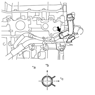
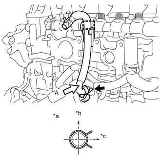
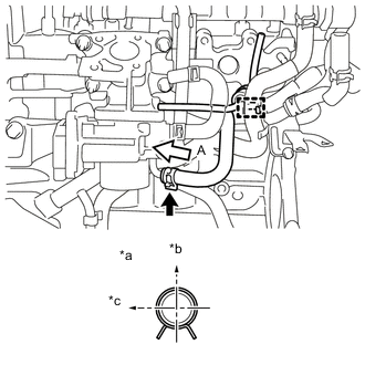
Text in Illustration *a View A *b Upper of Engine *c RH of Engine Install the water by-pass hose to the water by-pass pipe sub-assembly and slide the hose clip to secure it.
Note
Perform the installation with the hose clip at the correct angle.
-
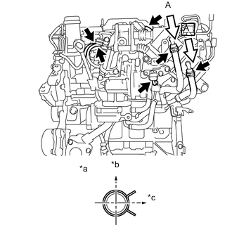
Install the water by-pass pipe sub-assembly to the No. 2 turbocharger stay, cylinder head sub-assembly, cylinder block sub-assembly and water inlet housing with the 3 bolts.
- Torque:
- 9.0 N*m { 92 kgf*cm, 80 in.*lbf }
Note
Make sure that the water by-pass pipe O-ring is not damaged or does not jump out of position during installation.
-
Install the 3 clamps to the water by-pass pipe sub-assembly.
-
-
INSTALL WATER BY-PASS HOSE
-
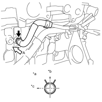
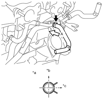
Text in Illustration *a View A *b Upper of Engine *c Front of Engine Connect the water by-pass hose to the tube connector and slide the hose clip to secure it.
Note
Perform the installation with the hose clip at the correct angle.
-
-
INSTALL NO. 6 WATER BY-PASS HOSE
-
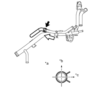
Text in Illustration *a View A *b View B *c Upper of Engine *d Front of Engine *e RH of Engine Install the No. 6 water by-pass hose to the water by-pass pipe sub-assembly and water outlet sub-assembly, and slide the 2 hose clips to secure it.
Note
Perform the installation with the hose clip at the correct angle.
-
-
INSTALL NO. 2 TURBO WATER HOSE
-
Text in Illustration *a View A *b Upper of Engine *c LH of Engine Install the No. 2 turbo water hose to the water by-pass pipe sub-assembly and slide the hose clip to secure it.
Note
Perform the installation with the hose clip at the correct angle.
-
-
INSTALL NO. 1 TURBO WATER HOSE
-
Text in Illustration *a View A *b Upper of Engine *c LH of Engine Install the No. 1 turbo water hose to the water by-pass pipe sub-assembly and slide the hose clip to secure it.
Note
Perform the installation with the hose clip at the correct angle.
-
-
INSTALL NO. 2 WATER BY-PASS HOSE
-
Text in Illustration *a View A *b Upper of Engine *c RH of Engine Install the No. 2 water by-pass hose to the water by-pass pipe sub-assembly and slide the hose clip to secure it.
Note
Perform the installation with the hose clip at the correct angle.
-
-
INSTALL NO. 3 WATER BY-PASS HOSE
-
Text in Illustration *a View A *b Upper of Engine *c Rear of Engine Install the No. 3 water by-pass hose to the water by-pass pipe sub-assembly and slide the hose clip to secure it.
Note
Perform the installation with the hose clip at the correct angle.
-
-
INSTALL NO. 2 OIL COOLER HOSE
-
Text in Illustration *a View A *b RH of Engine *c Front of Engine Install the No. 2 oil cooler hose to the oil filter bracket sub-assembly and slide the hose clip to secure it.
Note
Perform the installation with the hose clip at the correct angle.
-
Engage the 4 clamps to connect the No. 2 oil cooler hose to the 2 clamps and water by-pass pipe sub-assembly.
Note
Align the No. 2 oil cooler hose paint mark with the clamp center.
-
-
INSTALL OIL COOLER HOSE
-
Text in Illustration *a View A *b RH of Engine *c Front of Engine Install the oil cooler hose to the water by-pass pipe sub-assembly and oil cooler assembly, and slide the 2 hose clips to secure it.
Note
Perform the installation with the hose clip at the correct angle.
-
-
INSTALL INJECTION NOZZLE SEAT
-
INSTALL INJECTOR ASSEMBLY
-
INSTALL NOZZLE HOLDER CLAMP SEAT
-
INSTALL NO. 1 NOZZLE HOLDER CLAMP
-
INSTALL COMMON RAIL ASSEMBLY
-
Install the common rail assembly to the cylinder head sub-assembly with the 2 bolts.
- Torque:
- 21 N*m { 214 kgf*cm, 15 ft.*lbf }
-
Text in Illustration *a View A *b Upper of Engine *c Rear of Engine Install the No. 4 water by-pass hose to the water inlet pipe and slide the hose clip to secure it.
Note
Perform the installation with the hose clip at the correct angle.
-
Engage the hose clamp to connect the No. 4 water by-pass hose to the common rail assembly.
-
-
INSTALL GLOW PLUG ASSEMBLY
-
Clean the glow plug assembly installation holes in the cylinder head sub-assembly.
-
Using a deep socket wrench 10 mm, install the 4 glow plug assemblies to the cylinder head sub-assembly.
- Torque:
- 13 N*m { 127 kgf*cm, 9 ft.*lbf }
-
-
INSTALL NO. 1 GLOW PLUG CONNECTOR
-
Install the No. 1 glow plug connector to each glow plug assembly with the 4 nuts.
- Torque:
- 2.2 N*m { 22 kgf*cm, 19 in.*lbf }
-
Install the 4 glow plug screw grommets.
Tech Tips
Push the glow plug screw grommet into the threaded portion of the glow plug assembly by hand, and then turn it clockwise.
-
-
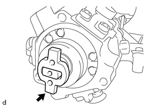
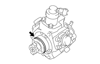
INSTALL SUPPLY PUMP ASSEMBLY
Note
If the supply pump drive coupling remained on the camshaft during removal, install the supply pump drive coupling to the supply pump assembly.
-
Apply a light coat of engine oil to the O-ring.
Note
If reusing the supply pump assembly, be sure to inspect the O-ring.
-
Install the supply pump assembly to the cylinder head sub-assembly and No. 3 camshaft bearing cap with the 3 bolts.
- Torque:
- 21 N*m { 214 kgf*cm, 15 ft.*lbf }
Note
Make sure that the O-ring is not damaged or does not jump out of position during installation.
-
-
INSTALL FUEL PUMP PROTECTOR
-
Install the fuel pump protector to the supply pump assembly with the 2 bolts.
- Torque:
- 10 N*m { 105 kgf*cm, 8 ft.*lbf }
-
-
INSTALL NO. 2 NOZZLE LEAKAGE PIPE
-
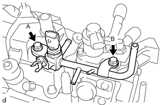
Install the No. 2 nozzle leakage pipe to the fuel pump protector and cylinder head cover sub-assembly with the 2 bolts.
- Torque:
- Bolt A
- 21 N*m { 214 kgf*cm, 15 ft.*lbf }
- Bolt B
- 9.0 N*m { 92 kgf*cm, 80 in.*lbf }
-
-
INSTALL NO. 1 FUEL HOSE
-
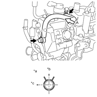
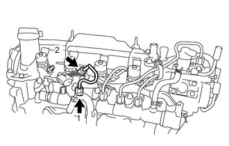
Text in Illustration *a View A *b Upper of Engine *c Rear of Engine Install a new gasket and No. 1 fuel hose to the supply pump assembly with the union bolt.
- Torque:
- 20 N*m { 204 kgf*cm, 15 ft.*lbf }
Note
Make sure the linking portion of the gasket is towards the bottom of the vehicle.
-
Connect the No. 1 fuel hose to the No. 2 nozzle leakage pipe and slide the hose clip to secure it.
Note
Perform the installation with the hose clip at the correct angle.
-
-
INSTALL NO. 2 FUEL HOSE
-
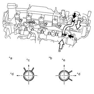
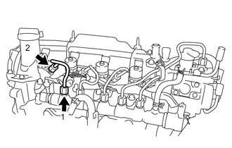
Text in Illustration *a View A *b View B *c Upper of Engine *d Rear of Engine *e LH of Engine Install the No. 2 fuel hose to the No. 2 nozzle leakage pipe and common rail assembly, and slide the 2 hose clips to secure it.
Note
Perform the installation with the hose clip at the correct angle.
-
-
INSTALL NO. 4 INJECTION PIPE SUB-ASSEMBLY
-
To prevent contamination by foreign matter, do not remove the plastic bag that was protecting the connector portion of the injector assembly and common rail assembly until immediately before installing the No. 4 injection pipe sub-assembly.
-
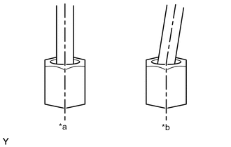
Text in Illustration *a Correct *b Incorrect Temporarily install new No. 4 injection pipe sub-assembly to the injector assembly and common rail assembly.
Note
-
When installing, the sealing surface of the No. 4 injection pipe sub-assembly should be fitted tightly against the injector assembly and common rail assembly.
-
When installing, do not tilt or angle the sealing surface of the No. 4 injection pipe sub-assembly.
-
When installing, tighten the union nut of the No. 4 injection pipe sub-assembly by hand until it cannot be turned any further.
-
-
Tighten the bolt of the No. 1 nozzle holder clamp.
- Torque:
- 19 N*m { 194 kgf*cm, 14 ft.*lbf }
-
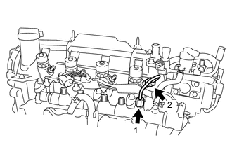
Using a union nut wrench 17 mm, fully tighten the 2 union nuts in the order shown in the illustration.
- Torque:
- Specified tightening torque
- 28 N*m { 286 kgf*cm, 21 ft.*lbf }
Note
When fully tightening the union nuts, make sure to tighten from the common rail assembly.
Tech Tips
-
Calculate the torque wrench reading when changing the fulcrum length of the torque wrench Click here.
-
When a union nut wrench 17 mm (fulcrum length of 30 mm (1.18 in.)) + torque wrench (fulcrum length of 180 mm (7.09 in.)): 24 N*m (245 kgf*cm, 18 ft.*lbf).
-
-
INSTALL FUEL INLET PIPE SUB-ASSEMBLY
-
To prevent contamination by foreign matter, do not remove the plastic bag that was protecting the connector portion of the injector assembly and common rail assembly until immediately before installing the fuel inlet pipe sub-assembly.
-
Text in Illustration *a Correct *b Incorrect Temporarily install new fuel inlet pipe sub-assembly to the supply pump assembly and common rail assembly.
Note
-
When installing, the sealing surface of the fuel inlet pipe sub-assembly should be fitted tightly against the injector assembly and common rail assembly.
-
When installing, do not tilt or angle the sealing surface of the fuel inlet pipe sub-assembly.
-
When installing, tighten the union nut of the fuel inlet pipe sub-assembly by hand until it cannot be turned any further.
-
-
Tighten the bolt of the No. 1 nozzle holder clamp.
- Torque:
- 19 N*m { 194 kgf*cm, 14 ft.*lbf }
-
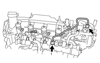
Using a union nut wrench 17 mm, fully tighten the 2 union nuts in the order shown in the illustration.
- Torque:
- Specified tightening torque
- 28 N*m { 286 kgf*cm, 21 ft.*lbf }
Note
When fully tightening the union nuts, make sure to tighten from the common rail assembly.
Tech Tips
-
Calculate the torque wrench reading when changing the fulcrum length of the torque wrench Click here.
-
When a union nut wrench 17 mm (fulcrum length of 30 mm (1.18 in.)) + torque wrench (fulcrum length of 180 mm (7.09 in.)): 24 N*m (245 kgf*cm, 18 ft.*lbf).
-
Install the No. 2 injection pipe clamp to the fuel inlet pipe sub-assembly and No. 4 injection pipe sub-assembly with the bolt.
- Torque:
- 5.0 N*m { 51 kgf*cm, 44 in.*lbf }
-
-
INSTALL NO. 3 INJECTION PIPE SUB-ASSEMBLY
-
To prevent contamination by foreign matter, do not remove the plastic bag that was protecting the connector portion of the injector assembly and common rail assembly until immediately before installing the No. 3 injection pipe sub-assembly.
-
Text in Illustration *a Correct *b Incorrect Temporarily install new No. 3 injection pipe sub-assembly to the injector assembly and common rail assembly.
Note
-
When installing, the sealing surface of the No. 3 injection pipe sub-assembly should be fitted tightly against the injector assembly and common rail assembly.
-
When installing, do not tilt or angle the sealing surface of the No. 3 injection pipe sub-assembly.
-
When installing, tighten the union nut of the No. 3 injection pipe sub-assembly by hand until it cannot be turned any further.
-
-
Tighten the bolt of the No. 1 nozzle holder clamp.
- Torque:
- 19 N*m { 194 kgf*cm, 14 ft.*lbf }
-
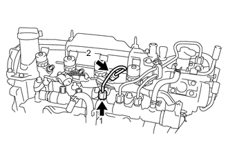
Using a union nut wrench 17 mm, fully tighten the 2 union nuts in the order shown in the illustration.
- Torque:
- Specified tightening torque
- 28 N*m { 286 kgf*cm, 21 ft.*lbf }
Note
When fully tightening the union nuts, make sure to tighten from the common rail assembly.
Tech Tips
-
Calculate the torque wrench reading when changing the fulcrum length of the torque wrench Click here.
-
When a union nut wrench 17 mm (fulcrum length of 30 mm (1.18 in.)) + torque wrench (fulcrum length of 180 mm (7.09 in.)): 24 N*m (245 kgf*cm, 18 ft.*lbf).
-
-
INSTALL NO. 2 INJECTION PIPE SUB-ASSEMBLY
-
To prevent contamination by foreign matter, do not remove the plastic bag that was protecting the connector portion of the injector assembly and common rail assembly until immediately before installing the No. 2 injection pipe sub-assembly.
-
Text in Illustration *a Correct *b Incorrect Temporarily install new No. 2 injection pipe sub-assembly to the injector assembly and common rail assembly.
Note
-
When installing, the sealing surface of the No. 2 injection pipe sub-assembly should be fitted tightly against the injector assembly and common rail assembly.
-
When installing, do not tilt or angle the sealing surface of the No. 2 injection pipe sub-assembly.
-
When installing, tighten the union nut of the No. 2 injection pipe sub-assembly by hand until it cannot be turned any further.
-
-
Tighten the bolt of the No. 1 nozzle holder clamp.
- Torque:
- 19 N*m { 194 kgf*cm, 14 ft.*lbf }
-
Using a union nut wrench 17 mm, fully tighten the 2 union nuts in the order shown in the illustration.
- Torque:
- Specified tightening torque
- 28 N*m { 286 kgf*cm, 21 ft.*lbf }
Note
When fully tightening the union nuts, make sure to tighten from the common rail assembly.
Tech Tips
-
Calculate the torque wrench reading when changing the fulcrum length of the torque wrench Click here.
-
When a union nut wrench 17 mm (fulcrum length of 30 mm (1.18 in.)) + torque wrench (fulcrum length of 180 mm (7.09 in.)): 24 N*m (245 kgf*cm, 18 ft.*lbf).
-
-
INSTALL NO. 1 INJECTION PIPE SUB-ASSEMBLY
-
To prevent contamination by foreign matter, do not remove the plastic bag that was protecting the connector portion of the injector assembly and common rail assembly until immediately before installing the No. 1 injection pipe sub-assembly.
-
Text in Illustration *a Correct *b Incorrect Temporarily install new No. 1 injection pipe sub-assembly to the injector assembly and common rail assembly.
Note
-
When installing, the sealing surface of the No. 1 injection pipe sub-assembly should be fitted tightly against the injector assembly and common rail assembly.
-
When installing, do not tilt or angle the sealing surface of the No. 1 injection pipe sub-assembly.
-
When installing, tighten the union nut of the No. 1 injection pipe sub-assembly by hand until it cannot be turned any further.
-
-
Tighten the bolt of the No. 1 nozzle holder clamp.
- Torque:
- 19 N*m { 194 kgf*cm, 14 ft.*lbf }
-
Using a union nut wrench 17 mm, fully tighten the 2 union nuts in the order shown in the illustration.
- Torque:
- Specified tightening torque
- 28 N*m { 286 kgf*cm, 21 ft.*lbf }
Note
When fully tightening the union nuts, make sure to tighten from the common rail assembly.
Tech Tips
-
Calculate the torque wrench reading when changing the fulcrum length of the torque wrench Click here.
-
When a union nut wrench 17 mm (fulcrum length of 30 mm (1.18 in.)) + torque wrench (fulcrum length of 180 mm (7.09 in.)): 24 N*m (245 kgf*cm, 18 ft.*lbf).
-
-
INSTALL NOZZLE LEAKAGE PIPE ASSEMBLY
Note
Perform installation and removal procedures by hand only. Do not use any tools.
-
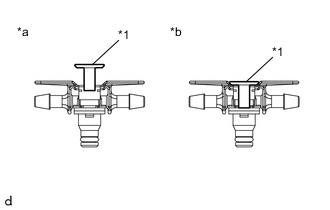
Text in Illustration *1 Lock Bush *a Correct *b Incorrect Check that the lock bush of the nozzle leakage pipe assembly is at the highest position.
-
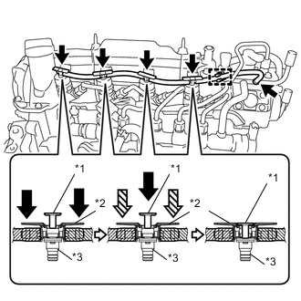
Text in Illustration *1 Lock Bush *2 Return Plug *3 Rest Arm 
Push 
Hold Insert the rest arm into the upper surface of the injector assembly, and while pressing the return plug from both sides, insert the nozzle leakage pipe assembly into each injector assembly.
-
While holding down the return plug, push the lock bush until it meets the top position of the return plug, and secure the nozzle leakage pipe assembly in place.
-
Engage the clamp to connect the nozzle leakage pipe assembly to the hose clamp.
-
Connect the nozzle leakage pipe assembly to the No. 2 nozzle leakage pipe and slide the hose clip to secure it.
-
-
INSTALL INTAKE AIR CONNECTOR WITH DIESEL THROTTLE BODY ASSEMBLY
-
Install a new intake air connector gasket to the cylinder head sub-assembly.
-
Install the intake air connector with diesel throttle body assembly to the cylinder head sub-assembly with the 2 bolts and 2 nuts.
- Torque:
- 23 N*m { 235 kgf*cm, 17 ft.*lbf }
-
Text in Illustration *a View A *b Upper of Engine *c LH of Engine Connect the No. 3 water by-pass hose to the intake air connector with diesel throttle body assembly and slide the hose clip to secure it.
Note
Perform the installation with the hose clip at the correct angle.
-
Engage the clamp to connect the vacuum transmitting hose assembly to the No. 2 oil cooler hose.
-
-
INSTALL ENGINE OIL LEVEL DIPSTICK GUIDE SUB-ASSEMBLY
-
Apply a light coat of engine oil to a new O-ring.
-
Install the O-ring to the engine oil level dipstick guide sub-assembly.
Note
Do not twist the O-ring.
-
Install the engine oil level dipstick guide sub-assembly to the intake air connector and oil pan sub-assembly with the bolt.
- Torque:
- 9.0 N*m { 92 kgf*cm, 80 in.*lbf }
Note
Make sure that the O-ring is not damaged or does not jump out of position during installation.
-
-
INSTALL ENGINE OIL LEVEL DIPSTICK SUB-ASSEMBLY
-
Install the engine oil level dipstick sub-assembly to the engine oil level dipstick guide sub-assembly.
-
-
INSTALL ELECTRIC EGR CONTROL VALVE ASSEMBLY
-
INSTALL WIRING HARNESS CLAMP BRACKET (for LHD)
-
Install the 2 wiring harness clamp brackets to the cylinder head cover sub-assembly with the 2 bolts.
- Torque:
- 8.4 N*m { 85 kgf*cm, 74 in.*lbf }
-
Connect the vacuum hose to the vacuum pump assembly.
-
-
INSTALL WIRING WIRE HARNESS CLAMP (for RHD)
-
Install the wiring harness clamp bracket to the cylinder head cover sub-assembly with the bolt.
- Torque:
- 8.4 N*m { 85 kgf*cm, 74 in.*lbf }
-
Connect the vacuum hose to the vacuum pump assembly.
-
-
INSTALL NO. 1 EGR COOLER BRACKET
-
Install the No. 1 EGR cooler bracket to the cylinder head sub-assembly with the 2 bolts.
- Torque:
- 23 N*m { 235 kgf*cm, 17 ft.*lbf }
-
-
INSTALL EGR WITH COOLER PIPE ASSEMBLY
-
Install a new EGR inlet gasket to the electric EGR control valve assembly.
-
Install a new EGR pipe gasket to the EGR with cooler pipe assembly.
-
Install the EGR with cooler pipe assembly to the electric EGR control valve assembly, No. 1 EGR cooler bracket and cylinder head sub-assembly with the 5 bolts and nut.
- Torque:
- 23 N*m { 235 kgf*cm, 17 ft.*lbf }
-
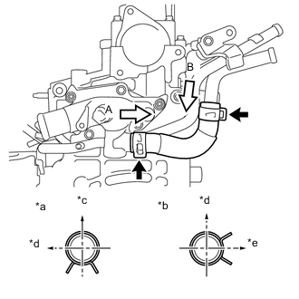
Text in Illustration *a View A *b RH of Engine *c Rear of Engine Connect the No. 2 water by-pass hose to the EGR with cooler pipe assembly and slide the hose clip to secure it.
Note
Perform the installation with the hose clip at the correct angle.
-
Connect the No. 2 oil cooler hose to the EGR with cooler pipe assembly and slide the hose clip to secure it.
Note
Perform the installation with the hose clip at the correct angle.
-
Connect the vacuum hose to the EGR with cooler pipe assembly.
-
Connect the 3 vacuum transmitting hoses to the EGR with cooler pipe assembly.
-
Engage the clamp to connect the connector to the EGR with cooler pipe assembly.
-
-
INSTALL GENERATOR BRACKET
-
Install the generator bracket to the cylinder block sub-assembly with the 2 bolts.
- Torque:
- 40 N*m { 407 kgf*cm, 30 ft.*lbf }
-
-
INSTALL GENERATOR ASSEMBLY
-
Install the generator assembly to the engine mounting bracket RH and generator bracket with the 2 bolts.
- Torque:
- 54 N*m { 551 kgf*cm, 40 ft.*lbf }
Bolt Length Bolt Length
mm (in.)
A 50 (1.969) B 80 (3.150) or 90 (3.543)
-
-
INSTALL ENGINE COVER BRACKET
-
Install the engine cover bracket to the engine mounting bracket RH with the bolt.
- Torque:
- 21 N*m { 214 kgf*cm, 15 ft.*lbf }
-