ENGINE UNIT(w/ DPF) REASSEMBLY

PROCEDURE
-
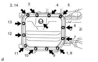
INSTALL OIL PAN SUB-ASSEMBLY
-
Remove any old packing material from the contact surface.
-
Apply a continuous bead of seal packing to the oil pan sub-assembly as shown in the illustration.
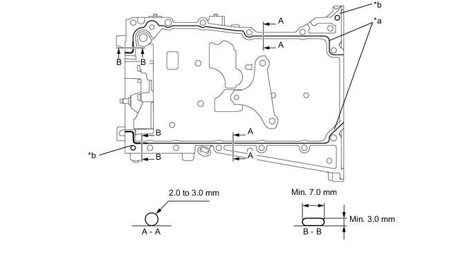
Text in Illustration *a Seal Packing *b Straight Pin Hole Standard Seal Diameter Area Bead Size
mm (in.)
A - A 2.0 to 3.0
(0.079 to 0.118)
B - B Min. Width: 7.0 (0.2756)
Min. Height: 3.0 (0.1181)
Seal packing Toyota Genuine Seal Packing Black, Three Bond 1207B or equivalent Note
-
If there is oil on the contact surfaces, wipe them with an oil-free cloth before applying seal packing.
-
When applying seal packing, make sure that it does not protrude into the 2 straight pin holes.
-
Install the oil pan sub-assembly within 3 minutes, and tighten the bolts within 10 minutes of applying the seal packing.
-
-
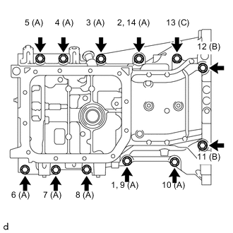
Using several steps, temporarily tighten the 12 bolts in the order shown in the illustration, and then tighten the bolts to the specified torque.
- Torque:
- 21 N*m { 214 kgf*cm, 15 ft.*lbf }
Bolt Length Bolt Length
mm (in.)
A 35 (1.378) B 143.7 (5.657) C 119 (4.685) Note
Wipe away any seal packing that is protruding from the front surface of the cylinder block sub-assembly before the seal packing hardens.
-
-
INSTALL ENGINE REAR OIL SEAL
-
INSTALL ENGINE OIL LEVEL SENSOR
-
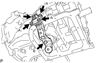
Temporarily tighten the engine oil level sensor to the oil pan sub-assembly with the 5 bolts.
-
Fully tighten the bolts A first, and then tighten bolt B.
- Torque:
- 11 N*m { 112 kgf*cm, 8 ft.*lbf }
-
-
INSTALL NO. 2 OIL PAN SUB-ASSEMBLY
-
Remove any old packing material from the contact surface.
-
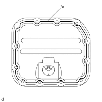
Text in Illustration *a Seal Packing Apply a continuous bead of seal packing (Diameter 2.5 to 3.5 mm (0.098 to 0.138 in.)) to the No. 2 oil pan sub-assembly as shown in the illustration.
Seal packing Toyota Genuine Seal Packing Black, Three Bond 1207B or equivalent Note
-
If there is oil on the contact surfaces, wipe them with an oil-free cloth before applying seal packing.
-
Install the No. 2 oil pan sub-assembly within 3 minutes, and tighten the bolts within 10 minutes of applying the seal packing.
-
-
Temporarily tighten the No. 2 oil pan sub-assembly to the oil pan sub-assembly with the 10 bolts and 2 nuts.
-
Fully tighten the 10 bolts and 2 nuts, in the order shown in the illustration.
- Torque:
- 9.0 N*m { 92 kgf*cm, 80 in.*lbf }
-
Install a new oil pan drain plug gasket and oil pan drain plug to the No. 2 oil pan sub-assembly.
- Torque:
- 38 N*m { 387 kgf*cm, 28 ft.*lbf }
-
-
SET OIL FILTER BRACKET SUB-ASSEMBLY
-
Check and clean the oil filter bracket sub-assembly installation surface.
-
Install a new oil filter bracket gasket to the oil pan sub-assembly.
-
Install the oil filter bracket sub-assembly to the oil pan sub-assembly with the 2 bolts.
- Torque:
- 21 N*m { 214 kgf*cm, 15 ft.*lbf }
-
-
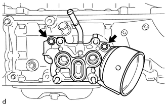
INSTALL OIL COOLER ASSEMBLY
-
Check and clean the oil cooler assembly installation surface.
-
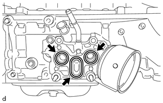
Install 2 new oil cooler O-rings and a new oil cooler gasket to the oil filter bracket sub-assembly.
-
Text in Illustration *1 Nut and Plate Washer Install the oil cooler assembly to the oil filter bracket sub-assembly with the 2 bolts, 2 nuts and 2 plate washers.
- Torque:
- 21 N*m { 214 kgf*cm, 15 ft.*lbf }
-
-
INSTALL OIL FILTER ELEMENT
-
INSTALL OIL FILTER CAP ASSEMBLY WITH ELEMENT
-
Using SST, tighten the oil filter cap assembly with element to the oil filter bracket sub-assembly.
- SST
- 09228-06501
- Torque:
- 25 N*m { 255 kgf*cm, 18 ft.*lbf }
-
-
INSTALL CYLINDER BLOCK WATER JACKET SPACER
-
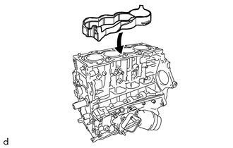
Install the cylinder block water jacket spacer to the cylinder block sub-assembly.
Note
Check that the top of the cylinder block water jacket spacer is settled below the top surface of the cylinder block sub-assembly.
-
-
INSTALL CYLINDER HEAD GASKET
-
INSTALL CYLINDER HEAD SUB-ASSEMBLY
Tech Tips
The cylinder head set bolts are tightened in multiple steps.
-
Place the cylinder head sub-assembly on the cylinder block sub-assembly.
-
Apply a light coat of engine oil to the threads of the cylinder head set bolts and area beneath the cylinder head set bolt heads that come in contact with the cylinder head set plate washers.
-
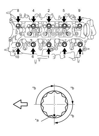
Text in Illustration 
Engine Front *a Paint Mark *b 90° Using several passes, uniformly install and tighten the 10 cylinder head set bolts and 10 new cylinder head set plate washers in the order shown in the illustration. (*1)
- Torque:
- 50 N*m { 510 kgf*cm, 37 ft.*lbf }
-
Mark the front of the cylinder head set bolts with paint.
-
Using the same sequence as step (*1), retighten the cylinder head set bolts by an additional 90° and repeat it 2 more times.
-
Check that each paint mark is now 270° from the front.
-
-
INSTALL NO. 1 VALVE ROCKER ARM SUB-ASSEMBLY
-
Apply engine oil to the valve stem caps, valve rocker arm pivot top surfaces and valve rocker arm roller portions.
-
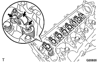
Install the 8 No. 1 valve rocker arm sub-assemblies to the cylinder head sub-assembly.
-
-
INSTALL CAMSHAFT
-
INSTALL CHAIN DAMPER SPRING
-
Install the chain damper spring to the chain tensioner plate.
-
-
INSTALL NO. 2 CHAIN SUB-ASSEMBLY
-
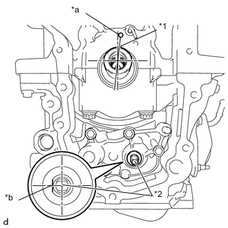
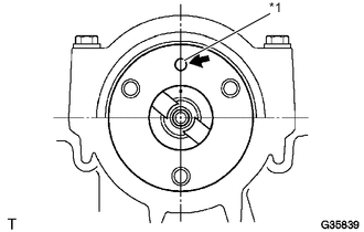
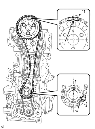
Text in Illustration *1 Key *2 Oil Pump Shaft *a TDC Mark *b Flat faces left Align the crankshaft key with the TDC mark on the cylinder block sub-assembly.
-
Rotate the oil pump shaft so that the flat faces left when viewing the cylinder block sub-assembly from the front.
-
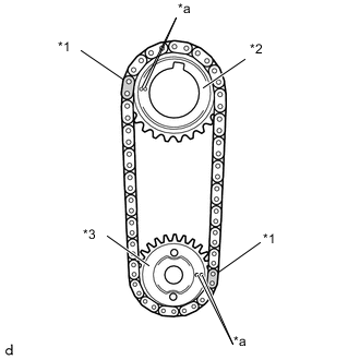
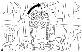
Text in Illustration *1 Mark Link *2 Oil Pump Drive Gear *3 Oil Pump Drive Shaft Gear *a Timing Mark Align the orange mark links with the timing marks of each gear as shown in the illustration.
-
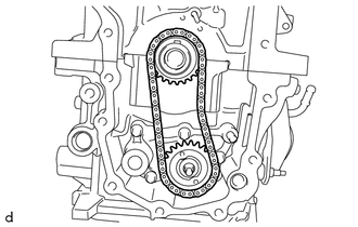
Install the oil pump drive gear and oil pump drive shaft gear onto the crankshaft and oil pump shaft with the No. 2 chain sub-assembly wrapped on the oil pump drive gear and oil pump drive shaft gear.
-
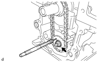
Insert a 4 mm (0.157 in.) diameter bar into the adjusting hole on the oil pump drive shaft gear to lock the oil pump drive shaft gear in position, and then tighten the nut.
- Torque:
- 30 N*m { 306 kgf*cm, 22 ft.*lbf }
-
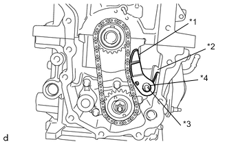
Text in Illustration *1 Chain Tensioner Plate *2 Chain Damper Spring *3 Pin *4 Pivot Hole Install the chain tensioner plate with chain damper spring to the pin.
Tech Tips
-
Push the chain tensioner plate so that the area around the pivot hole reaches the base of the pin.
-
The end of the chain damper spring should contact the side of the oil pan sub-assembly so that tension is applied to the chain.
-
-
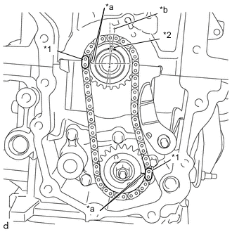
Text in Illustration *1 Mark Link *2 Key *a Timing Mark *b TDC Mark Check that the mark plate and timing mark are in the positions shown in the illustration.
-
-
INSTALL CHAIN SUB-ASSEMBLY
-
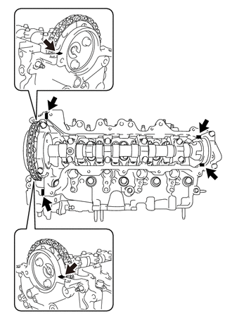
Text in Illustration *1 Straight Pin Turn the camshaft to set the straight pin in the position shown in the illustration.
-
Text in Illustration *1 Key *a TDC Mark 
Turn Turn the crankshaft to set the key in the position shown in the illustration.
-
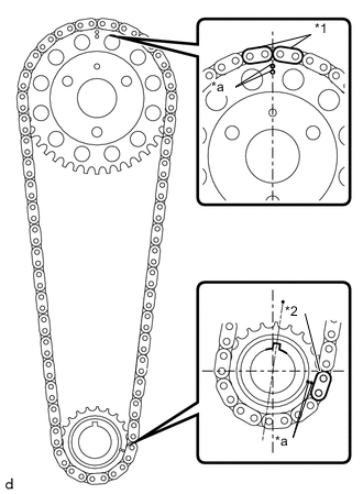
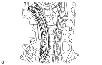
Text in Illustration *1 Yellow Mark Plate *2 Pink Mark Plate *a Timing Mark Align the chain's 2 yellow mark plates with the timing mark on the camshaft timing sprocket, and pink mark plate with the timing mark on the crankshaft timing sprocket.
-
Install the camshaft timing sprocket and crankshaft timing sprocket onto the camshaft and crankshaft with the chain sub-assembly wrapped on the camshaft timing sprocket and crankshaft timing sprocket.
-
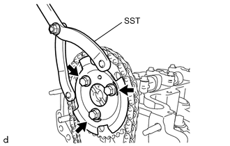
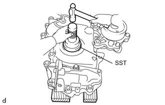
Using SST, fix the camshaft timing sprocket, and install the camshaft timing sprocket and No. 2 crank angle sensor plate to the camshaft with the 3 bolts.
- SST
- 09960-10010 ( 09962-01000, 09963-01000 )
- Torque:
- 20 N*m { 204 kgf*cm, 15 ft.*lbf }
Note
Check that the contact surfaces of the No. 2 crank angle sensor plate and camshaft timing sprocket are securely contacting, and then tighten the bolt.
-
-
INSTALL NO. 1 CHAIN VIBRATION DAMPER
-
Using an 8 mm socket hexagon wrench, install the No. 1 chain vibration damper to the cylinder head sub-assembly and cylinder block sub-assembly with the 2 bolts.
- Torque:
- 21 N*m { 214 kgf*cm, 15 ft.*lbf }
-
-
INSTALL CHAIN TENSIONER SLIPPER
-
Install the chain tensioner slipper onto the cylinder head sub-assembly.
-
-
INSTALL NO. 1 CHAIN TENSIONER ASSEMBLY
-
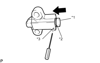
Text in Illustration *1 Plunger *2 Groove *3 Hole Push Push in the plunger until the groove is aligned with the tensioner hole, and then insert a 1.1 mm (0.043 in.) diameter bar.
-
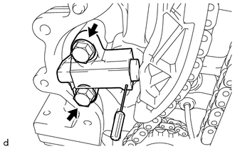
Install the No. 1 chain tensioner assembly to the cylinder block sub-assembly with the 2 bolts.
- Torque:
- 21 N*m { 214 kgf*cm, 15 ft.*lbf }
-
Remove the 1.1 mm (0.043 in.) diameter bar from the No. 1 chain tensioner assembly.
-
Text in Illustration *1 Yellow Mark Plate *2 Pink Mark Plate *a Timing Mark Check that the mark plate and timing mark are in the positions shown in the illustration.
-
-
INSTALL WATER INLET HOUSING
-
Install a new No. 2 water inlet housing gasket to the water inlet housing.
-
Install the water inlet housing to the timing chain cover assembly with the 3 bolts.
- Torque:
- 9.0 N*m { 92 kgf*cm, 80 in.*lbf }
Note
Do not reuse a water inlet housing that has been dropped.
-
-
INSTALL OIL CHECK VALVE SUB-ASSEMBLY
-
Using a 5 mm socket hexagon wrench, install the oil check valve sub-assembly to the timing chain cover assembly with the bolt.
- Torque:
- 9.0 N*m { 92 kgf*cm, 80 in.*lbf }
-
-
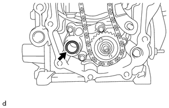
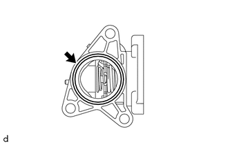
INSTALL TIMING CHAIN COVER OIL SEAL
-
Using SST and a hammer, tap in a new timing chain cover oil seal until its surface is flush with the timing chain cover assembly edge.
- SST
- 09223-22010
Timing chain cover oil seal tap in depth -0.6 to 0 mm (-0.0236 to 0 in.) Note
-
Keep the timing chain cover oil seal lip free from foreign matter.
-
Do not tap the timing chain cover oil seal at an angle.
-
Apply MP grease to the timing chain cover oil seal lip.
Note
Keep the lip free of foreign matter.
-
-
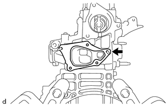
INSTALL TIMING CHAIN COVER ASSEMBLY
-
Install a new oil pump gasket to the oil pan sub-assembly.
-
Remove any old packing material from the contact surface.
-
Apply seal packing to the engine body and timing chain cover assembly as shown in the illustration below.
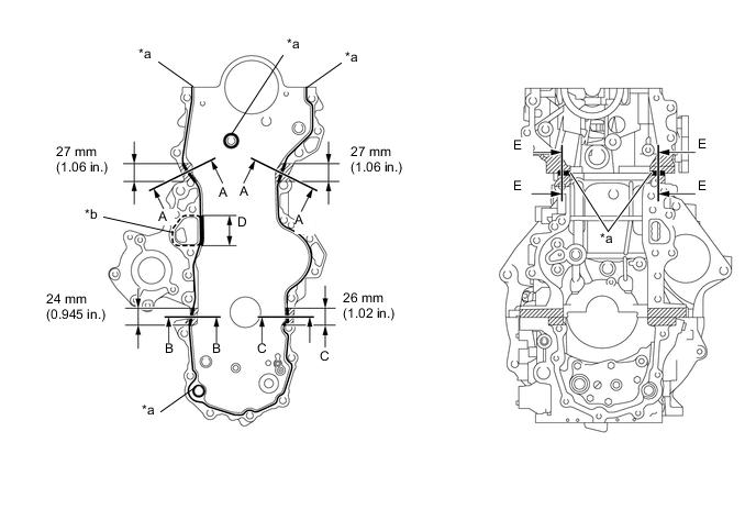
Text in Illustration *a Toyota Genuine Seal Packing Black, Three Bond 1207B or equivalent *b Toyota Genuine Seal Packing 1282B, Three Bond 1282B or equivalent Seal packing Water pump part: Toyota Genuine Seal Packing 1282B, Three Bond 1282B or equivalent Other part: Toyota Genuine Seal Packing Black, Three Bond 1207B or equivalent Note
-
If there is oil on the contact surfaces, wipe them with an oil-free cloth before applying seal packing.
-
Install the timing chain cover assembly within 3 minutes, and tighten the bolts within 10 minutes of applying the seal packing.
Tech Tips
Areas A-A, B-B and C-C are the joints between the cylinder block sub-assembly and cylinder head sub-assembly, and the cylinder block sub-assembly and oil pan sub-assembly.
Application Specification Area Seal Packing Diameter Seal Packing Dimension Seal Packing Application Length Continuous Line Area Except A-A, B-B, C-C and D 3.5 to 4.5 mm (0.138 to 0.177 in.) - - Dashed Line Area 3.5 to 4.5 mm (0.138 to 0.177 in.) - - A-A - Width: 15 mm (0.591 in.)
Height: 4.5 mm (0.177 in.)
27 mm (1.06 in.) B-B - Width: 7.0 mm (0.276 in.)
Height: 3.5 mm (0.138 in.)
24 mm (0.945 in.) C-C - Width: 7.0 mm (0.276 in.)
Height: 3.5 mm (0.138 in.)
26 mm (1.02 in.) D 3.0 to 4.0 mm (0.118 to 0.157 in.): Double Line Area - 45.1 mm (1.78 in.) E-E 3.5 to 4.5 mm (0.138 to 0.177 in.) - - -
-
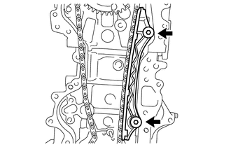
Install the timing chain cover assembly to the cylinder head sub-assembly, cylinder block sub-assembly and oil pan sub-assembly with the 20 bolts and 2 nuts, in the order shown in the illustration.
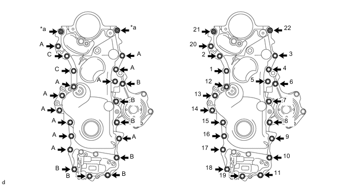
Text in Illustration *a Nut - - - Torque:
- Bolt A, B, Nut
- 18 N*m { 184 kgf*cm, 13 ft.*lbf }
- Bolt C
- 31 N*m { 316 kgf*cm, 23 ft.*lbf }
Bolt Length Bolt Length
mm (in.)
A 25 (0.984) B 40 (1.575) C 41 (1.614) Note
-
Make sure that the chain does not come into contact with the seal packing when installing the timing chain cover assembly.
-
Install the engine mounting bracket RH and engine water pump assembly within 10 minutes of installing the timing chain cover assembly.
-
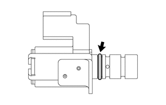
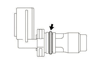
Apply a light coat of engine oil to the O-ring of the oil pressure switching valve assembly.
Note
If reusing the oil pressure switching valve assembly, be sure to inspect the O-ring.
-
Install the oil pressure switching valve assembly to the timing chain cover assembly with the bolt.
- Torque:
- 9.0 N*m { 92 kgf*cm, 80 in.*lbf }
Note
-
If a component has been dropped or subjected to a strong impact, replace the oil pressure switching valve assembly.
-
Make sure that the O-ring is not damaged or does not jump out of position during installation.
-
-
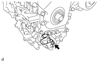
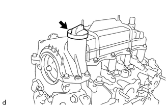
INSTALL CAMSHAFT POSITION SENSOR
-
Apply a light coat of engine oil to the O-ring of the camshaft position sensor.
Note
If reusing the camshaft position sensor, be sure to inspect the O-ring.
-
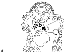
Install the camshaft position sensor to the timing chain cover assembly with the bolt.
- Torque:
- 7.0 N*m { 71 kgf*cm, 62 in.*lbf }
Note
-
If a component has been dropped or subjected to a strong impact, replace the camshaft position sensor.
-
Make sure that the O-ring is not damaged or does not jump out of position during installation.
-
-
INSTALL CRANKSHAFT DAMPER SUB-ASSEMBLY
-
INSTALL NO. 2 TIMING CHAIN COVER
-
Install the No. 2 timing chain cover to the timing chain cover assembly.
-
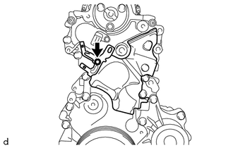
Install the manifold temperature sensor bracket to the timing chain cover assembly with the bolt.
- Torque:
- 9.0 N*m { 92 kgf*cm, 80 in.*lbf }
-
-
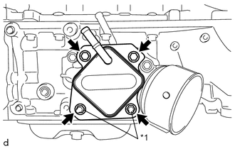
INSTALL ENGINE MOUNTING BRACKET RH
-
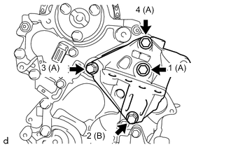
Temporarily tighten the engine mounting bracket to the timing chain cover assembly with the 4 bolts.
Bolt Length Bolt Length
mm (in.)
A 55 (2.165) B 70 (2.756) -
Fully tighten the 4 bolts, in the order shown in the illustration.
- Torque:
- 55 N*m { 561 kgf*cm, 41 ft.*lbf }
-
-
CHECK VALVE CLEARANCE
-
ADJUST VALVE CLEARANCE
-
INSTALL CYLINDER HEAD COVER SUB-ASSEMBLY
-
Install a new cylinder head cover gasket onto the cylinder head cover sub-assembly.
Note
-
Remove any oil from the contact surfaces.
-
Check that the cylinder head cover gasket is securely installed into the groove of the cylinder head cover sub-assembly.
-
-
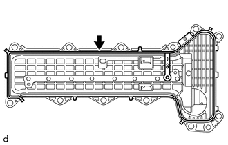
Remove any old packing material from the contact surface.
-
Apply seal packing to the 6 locations shown in the illustration.
Text in Illustration Seal Packing Seal packing Toyota Genuine Seal Packing Black, Three Bond 1207B or equivalent Note
-
If there is oil on the contact surfaces, wipe them with an oil-free cloth before applying seal packing.
-
Install the cylinder head cover sub-assembly within 3 minutes, and tighten the bolts within 10 minutes of applying the seal packing.
-
-
Temporarily install the cylinder head cover sub-assembly to the cylinder head sub-assembly with the 11 bolts and nut.
-
Temporarily tighten the bolt A.
-
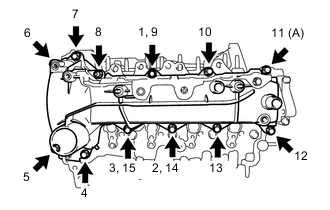
Fully tighten the 11 bolts and nut, in the order shown in the illustration.
- Torque:
- 10 N*m { 102 kgf*cm, 7 ft.*lbf }
-
-
INSTALL OIL FILLER CAP SUB-ASSEMBLY
-
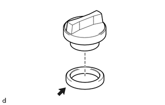
Install the oil filler cap gasket onto the oil filler cap sub-assembly.
-
Install the oil filler cap sub-assembly onto the cylinder head cover sub-assembly.
-
-
INSTALL OIL PRESSURE SENDER GAUGE ASSEMBLY
-
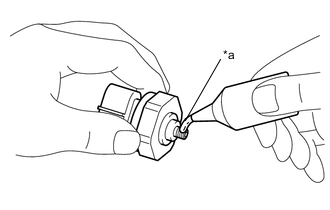
Text in Illustration *a Adhesive Apply adhesive to 2 or 3 threads of the oil pressure sender gauge assembly.
Adhesive Toyota Genuine Adhesive 1344, Three Bond 1344 or equivalent Note
To prevent contamination by foreign matter, install immediately after applying adhesive.
-
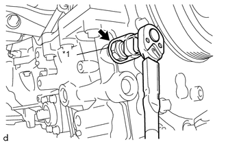
Text in Illustration *1 27 mm Deep Socket Wrench Using a 27 mm deep socket wrench, install the oil pressure sender gauge assembly to the oil pan sub-assembly.
- Torque:
- 15 N*m { 153 kgf*cm, 11 ft.*lbf }
Note
If a component has been dropped or subject to a strong impact, replace the oil pressure sender gauge assembly.
-
-
INSTALL WATER INLET
-
Install a new No. 1 water inlet housing gasket to the water inlet.
-
Install the water inlet to the water inlet housing with the 3 bolts.
- Torque:
- 9.0 N*m { 92 kgf*cm, 80 in.*lbf }
Note
Do not reuse a water inlet that has been dropped.
-
-
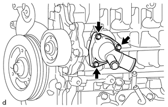
INSTALL WATER OUTLET SUB-ASSEMBLY
-
Install a new water outlet gasket to the cylinder head sub-assembly.
-
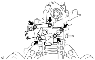
Install the water outlet sub-assembly to the cylinder head sub-assembly with the 3 bolts and 2 nuts.
- Torque:
- 11 N*m { 112 kgf*cm, 8 ft.*lbf }
-
-
INSTALL ENGINE COOLANT TEMPERATURE SENSOR
-
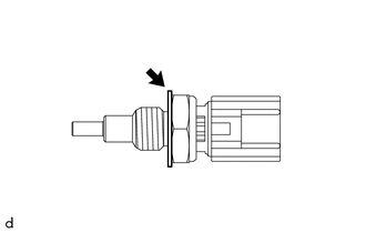
Install a new gasket to the engine coolant temperature sensor.
-
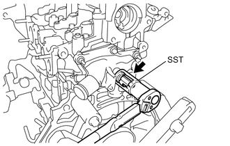
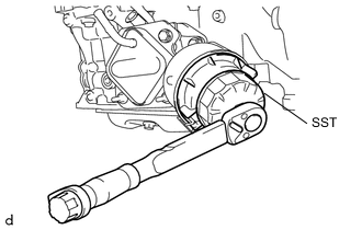
Using SST, install the engine coolant temperature sensor to the water outlet sub-assembly.
- SST
- 09817-33190
- Torque:
- 20 N*m { 204 kgf*cm, 15 ft.*lbf }
Note
If a component has been dropped or subjected to a strong impact, replace the engine coolant temperature sensor.
-