PROCEDURE
- Click here
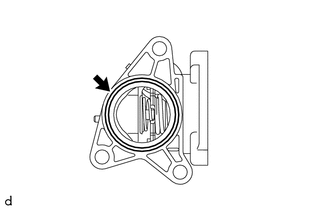
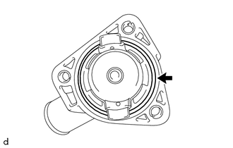
REMOVE ENGINE COOLANT TEMPERATURE SENSOR
-
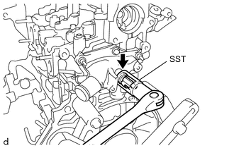
Using SST, remove the engine coolant temperature sensor from the water outlet sub-assembly.
09817-33190 Note:If a component has been dropped or subjected to a strong impact, replace the engine coolant temperature sensor.
-
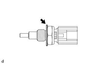
Remove the gasket from the engine coolant temperature sensor.
-
- Click here
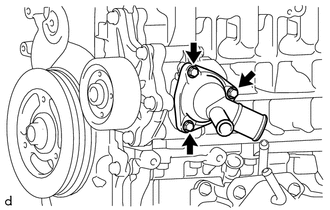
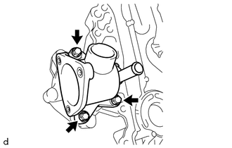
REMOVE WATER OUTLET SUB-ASSEMBLY
-
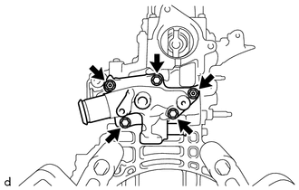
Remove the 3 bolts, 2 nuts and water outlet sub-assembly from the cylinder head sub-assembly.
-
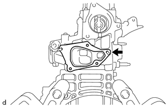
Remove the water outlet gasket from the cylinder head sub-assembly.
-
- Click here
REMOVE WATER INLET
-
Remove the 3 bolts and water inlet from the water inlet housing.
-
Remove the No. 1 water inlet housing gasket from the water inlet.
-
- Click here
REMOVE OIL PRESSURE SENDER GAUGE ASSEMBLY
-
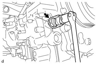
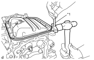
Using a 27 mm deep socket wrench, remove the oil pressure sender gauge assembly from the oil pan sub-assembly.
Table 1. Text in Illustration *1 27 mm Deep Socket Wrench Note:If a component has been dropped or subjected to a strong impact, replace the oil pressure sender gauge assembly.
-
- Click here
REMOVE OIL FILLER CAP SUB-ASSEMBLY
-
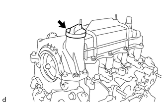
Remove the oil filler cap sub-assembly from the cylinder head cover sub-assembly.
-
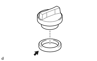
Remove the oil filler cap gasket from the oil filler cap sub-assembly.
-
- Click here
REMOVE CYLINDER HEAD COVER SUB-ASSEMBLY
-
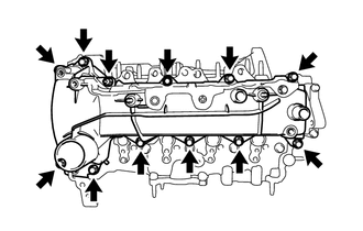
Remove the 11 bolts, nut and cylinder head cover sub-assembly from the cylinder head sub-assembly.
-
Remove the cylinder head cover gasket from the cylinder head cover sub-assembly.
-
- Click here
REMOVE ENGINE MOUNTING BRACKET RH
-
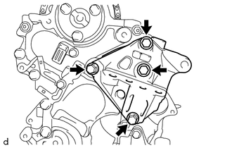
Remove the 4 bolts and engine mounting bracket RH from the timing chain cover assembly.
-
- Click here
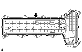
REMOVE NO. 2 TIMING CHAIN COVER
-
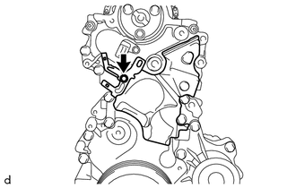
Remove the bolt and manifold temperature sensor bracket from the timing chain cover assembly.
-
Remove the No. 2 timing chain cover from the timing chain cover assembly.
-
- Click here
REMOVE CAMSHAFT POSITION SENSOR
-
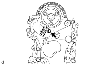
Remove the bolt and camshaft position sensor from the timing chain cover assembly.
Note:If a component has been dropped or subjected to a strong impact, replace the camshaft position sensor.
-
- Click here
REMOVE CRANKSHAFT DAMPER SUB-ASSEMBLY
- Click here
REMOVE TIMING CHAIN COVER ASSEMBLY
-
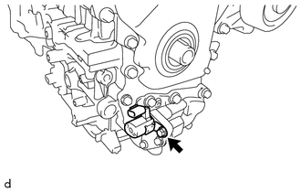
Remove the bolt and oil pressure switching valve assembly from the timing chain cover assembly.
Note:If a component has been dropped or subjected to a strong impact, replace the oil pressure switching valve assembly.
-
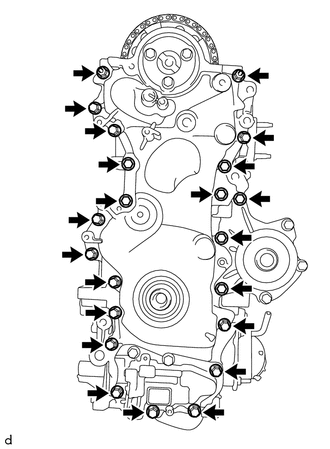
Remove the 20 bolts and 2 nuts.
-
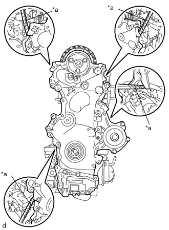
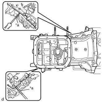
Using a screwdriver with its tip wrapped in protective tape, remove the timing chain cover assembly by prying between the timing chain cover assembly, cylinder head sub-assembly and cylinder block sub-assembly.
Table 2. Text in Illustration *a Protective Tape Note:Do not damage the contact surfaces of the timing chain cover assembly, cylinder head sub-assembly and cylinder block sub-assembly.
-
Remove the oil pump gasket from the oil pan sub-assembly.
-
- Click here
REMOVE TIMING CHAIN COVER OIL SEAL
-
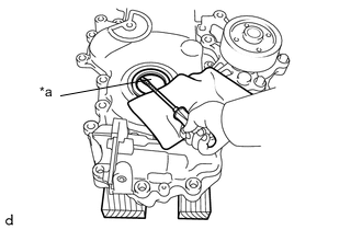
Using a screwdriver with its tip wrapped in protective tape, remove the timing chain cover oil seal from the timing chain cover assembly.
Table 3. Text in Illustration *a Protective Tape
-
- Click here
REMOVE OIL CHECK VALVE SUB-ASSEMBLY
-
Using a 5 mm socket hexagon wrench, remove the bolt and oil check valve sub-assembly from the timing chain cover assembly.
-
- Click here
REMOVE WATER INLET HOUSING
-
Remove the 3 bolts and water inlet housing from the timing chain cover assembly.
-
Remove the No. 2 water inlet housing gasket from the water inlet housing.
-
- Click here
REMOVE NO. 1 CHAIN TENSIONER ASSEMBLY
Note:Do not rotate the crankshaft with the No. 1 chain tensioner assembly removed.
-
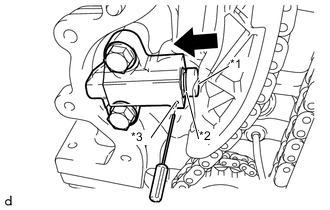
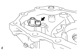
Push in the plunger until the groove is aligned with the hole, and then insert a 1.1 mm (0.043 in.) diameter bar.
Table 4. Text in Illustration *1 Plunger *2 Groove *3 Hole 
Push -
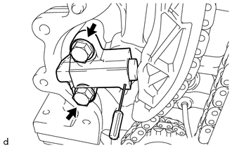
Remove the 2 bolts and No. 1 chain tensioner assembly from the cylinder block sub-assembly.
-
- Click here
REMOVE CHAIN TENSIONER SLIPPER
-
Remove the chain tensioner slipper from the cylinder head sub-assembly.
-
- Click here
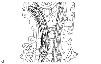
REMOVE NO. 1 CHAIN VIBRATION DAMPER
-
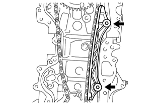
Using an 8 mm socket hexagon wrench, remove the 2 bolts and No. 1 chain vibration damper from the cylinder head sub-assembly and cylinder block sub-assembly.
-
- Click here
REMOVE CHAIN SUB-ASSEMBLY
-
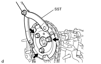
Using SST, hold the camshaft timing sprocket.
09960-10010 09962-01000 09963-01000 -
Remove the 3 bolts and No. 2 crank angle sensor plate.
-
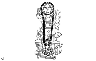
Remove the camshaft timing sprocket, crankshaft timing sprocket and chain sub-assembly together.
-
- Click here
REMOVE NO. 2 CHAIN SUB-ASSEMBLY
-
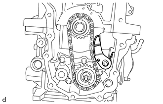
Remove the chain tensioner plate with chain damper spring from the pin.
-
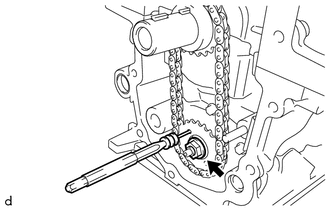
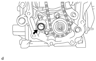
Insert a 4 mm (0.157 in.) diameter bar into the adjusting hole of the oil pump drive shaft gear to lock the oil pump drive shaft gear in position, and then remove the nut.
-
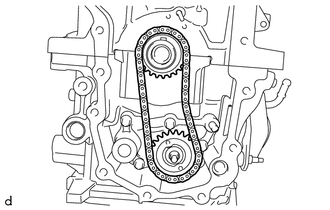
Remove the oil pump drive gear, oil pump drive shaft gear and No. 2 chain sub-assembly together.
-
- Click here
REMOVE CHAIN DAMPER SPRING
-
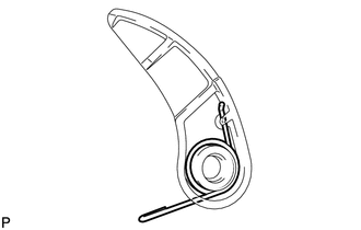
Remove the chain damper spring from the chain tensioner plate.
-
- Click here
REMOVE CAMSHAFT
- Click here
REMOVE NO. 1 VALVE ROCKER ARM SUB-ASSEMBLY
-
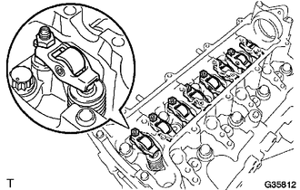
Remove the 8 No. 1 valve rocker arm sub-assembly from the cylinder head sub-assembly.
-
- Click here
REMOVE CYLINDER HEAD SUB-ASSEMBLY
-
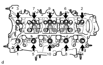
Using several steps, loosen the 10 cylinder head set bolts in the order shown in the illustration, and then remove the 10 cylinder head set bolts and 10 cylinder head set plate washers.
Note:
-
When removing the cylinder head set bolts, do not drop the cylinder head set plate washers into the engine.
-
Removing the cylinder head set bolts in the wrong order may cause damage to the cylinder head sub-assembly.
-
-
Remove the cylinder head sub-assembly from the cylinder block sub-assembly.
-
- Click here
REMOVE CYLINDER HEAD GASKET
- Click here
REMOVE CYLINDER BLOCK WATER JACKET SPACER
-
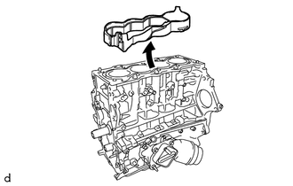
Remove the cylinder block water jacket spacer from the cylinder block sub-assembly.
-
- Click here
REMOVE OIL FILTER CAP ASSEMBLY WITH ELEMENT
-
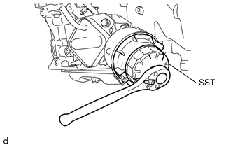
Using SST, remove the oil filter cap assembly with element from the oil filter bracket sub-assembly.
09228-06501
-
- Click here
REMOVE OIL FILTER ELEMENT
- Click here
REMOVE OIL COOLER ASSEMBLY
-
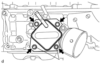
Remove the 2 bolts, 2 nuts, 2 plate washers and oil cooler assembly from the oil filter bracket sub-assembly.
Table 5. Text in Illustration *1 Nut and Plate Washer -
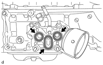
Remove the 2 oil cooler O-rings and oil cooler gasket from the oil filter bracket sub-assembly.
-
- Click here
REMOVE OIL FILTER BRACKET SUB-ASSEMBLY
-
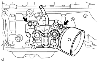
Remove the 2 bolts and oil filter bracket sub-assembly from the oil pan sub-assembly.
-
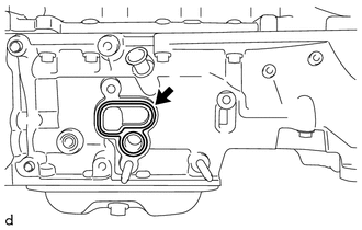
Remove the oil filter bracket gasket from the oil pan sub-assembly.
-
- Click here
REMOVE NO. 2 OIL PAN SUB-ASSEMBLY
-
Remove the oil pan drain plug and oil pan drain plug gasket from the No. 2 oil pan sub-assembly.
-
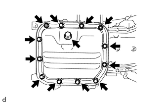
Remove the 10 bolts and 2 nuts.
-
Insert the oil pan seal cutter blade between the oil pan sub-assembly and No. 2 oil pan sub-assembly, and cut off the applied sealer.
Table 6. Text in Illustration *1 Oil Pan Seal Cutter Note:Do not damage the contact surface of the oil pan sub-assembly and No. 2 oil pan sub-assembly.
-
Remove the No. 2 oil pan sub-assembly from the oil pan sub-assembly.
-
- Click here
REMOVE ENGINE OIL LEVEL SENSOR
-
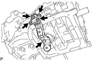
Remove the 5 bolts and engine oil level sensor from the oil pan sub-assembly.
-
- Click here
REMOVE OIL PAN SUB-ASSEMBLY
-
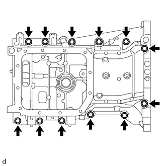
Remove the 12 bolts.
-
Using a screwdriver with its tip wrapped in protective tape, remove the oil pan sub-assembly by prying between the cylinder block sub-assembly and oil pan sub-assembly.
Table 7. Text in Illustration *a Protective Tape Note:
-
Do not apply excessive force when prying between the cylinder block sub-assembly and oil pan sub-assembly.
-
Do not damage the contact surface of the cylinder block sub-assembly and oil pan sub-assembly.
-
-
- Click here
REMOVE ENGINE REAR OIL SEAL
-
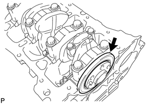
Remove the engine rear oil seal from the crankshaft and cylinder block sub-assembly.
-