ENGINE UNIT(w/ DPF) REMOVAL

PROCEDURE
-
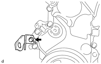
REMOVE ENGINE COVER BRACKET
-
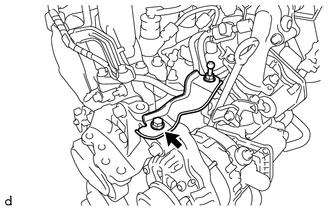
Remove the bolt and engine cover bracket from the engine mounting bracket RH.
-
-
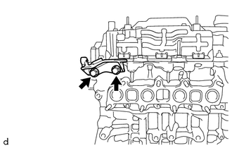
REMOVE GENERATOR ASSEMBLY
-
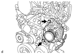
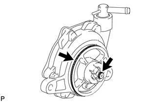
Remove the 2 bolts and generator assembly from the engine mounting bracket RH and generator bracket.
-
-
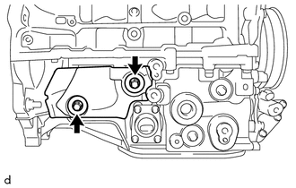
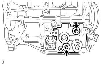
REMOVE GENERATOR BRACKET
-
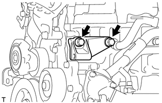
Remove the 2 bolts and generator bracket from the cylinder block sub-assembly.
-
-
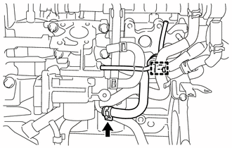
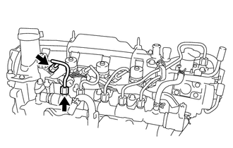
REMOVE EGR WITH COOLER PIPE ASSEMBLY
-
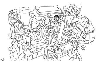
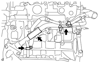
Disengage the clamp to separate the connector from the EGR with cooler pipe assembly.
-
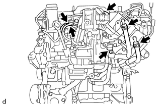
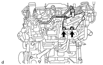
Disconnect the 3 vacuum transmitting hoses from the EGR with cooler pipe assembly.
-
Disconnect the vacuum hose from the EGR with cooler pipe assembly.
-
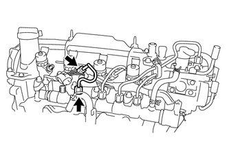
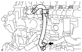
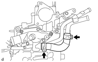
Slide the hose clip and disconnect the No. 2 oil cooler hose from the EGR with cooler pipe assembly.
-
Slide the hose clip and disconnect the No. 2 water by-pass hose from the EGR with cooler pipe assembly.
-
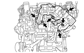
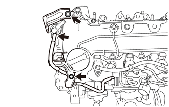
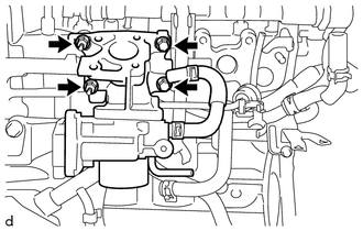
Remove the 5 bolts, nut and EGR with cooler pipe assembly from the electric EGR control valve assembly, No. 1 EGR cooler bracket and cylinder head sub-assembly.
-
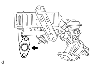
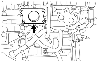
Remove the EGR pipe gasket from the EGR with cooler pipe assembly.
-
Remove the EGR inlet gasket from the electric EGR control valve assembly.
-
-
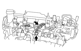
REMOVE NO. 1 EGR COOLER BRACKET
-
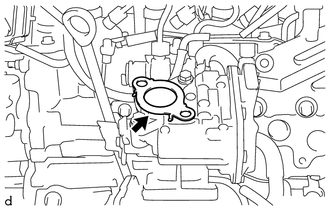
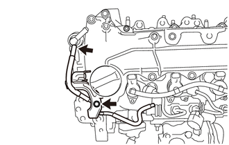
Remove the 2 bolts and No. 1 EGR cooler bracket from the cylinder head sub-assembly.
-
-
REMOVE WIRING HARNESS CLAMP BRACKET (for LHD)
-
Disconnect the vacuum hose from the vacuum pump assembly.
-
Remove the 2 bolts and 2 wiring harness clamp brackets from the cylinder head cover sub-assembly.
-
-
REMOVE WIRING HARNESS CLAMP BRACKET (for RHD)
-
Disconnect the vacuum hose from the vacuum pump assembly.
-
Remove the bolt and wiring harness clamp bracket from the cylinder head cover sub-assembly.
-
-
REMOVE ELECTRIC EGR CONTROL VALVE ASSEMBLY
-
REMOVE ENGINE OIL LEVEL DIPSTICK SUB-ASSEMBLY
-
Remove the engine oil level dipstick sub-assembly from the engine oil level dipstick guide sub-assembly.
-
-
REMOVE ENGINE OIL LEVEL DIPSTICK GUIDE SUB-ASSEMBLY
-
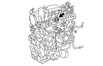
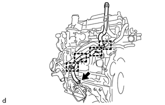
Remove the bolt and engine oil level dipstick guide sub-assembly from the intake air connector and oil pan sub-assembly.
-

Remove the O-ring from the engine oil level dipstick guide sub-assembly.
-
-
REMOVE INTAKE AIR CONNECTOR WITH DIESEL THROTTLE BODY ASSEMBLY
-
Disengage the clamp to separate the vacuum transmitting hose assembly from the No. 2 oil cooler hose.
-
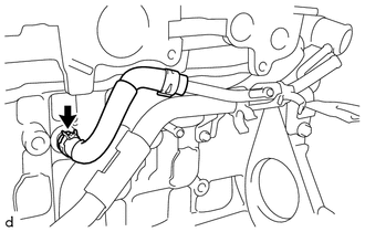
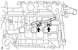
Slide the hose clip and disconnect the No. 3 water by-pass hose from the intake air connector with diesel throttle body assembly.
-
Remove the 2 bolts, 2 nuts and intake air connector with diesel throttle body assembly from the cylinder head sub-assembly.
-
Remove the intake air connector gasket from the cylinder head sub-assembly.
-
-
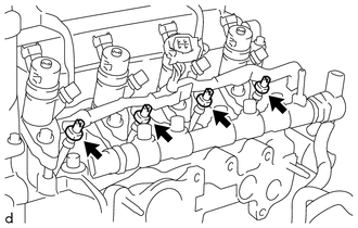
REMOVE NOZZLE LEAKAGE PIPE ASSEMBLY
-
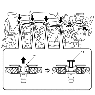
Text in Illustration *1 Lock Bush 
Pull Up Slide the hose clip and disconnect the nozzle leakage pipe assembly from the No. 2 nozzle leakage pipe.
-
Disengage the clamp to separate the nozzle leakage pipe assembly from hose clamp.
-
Pull up the 4 lock bushes of the nozzle leakage pipe assembly as shown in the illustration, and remove it from each injector assembly.
-
-
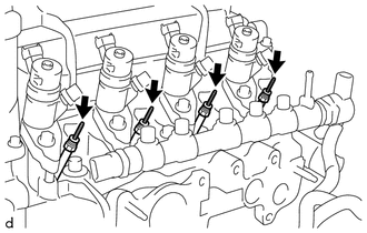
REMOVE NO. 1 INJECTION PIPE SUB-ASSEMBLY
-
Using a union nut wrench 17 mm, loosen the 2 union nuts in the order shown in the illustration, and remove the No. 1 injection pipe sub-assembly from the injector assembly and common rail assembly.
Note
To prevent contamination by foreign matter, after removing the No. 1 injection pipe sub-assembly, protect the connecting portions of the injector assembly and common rail assembly with plastic bags.
-
-
REMOVE NO. 2 INJECTION PIPE SUB-ASSEMBLY
-
Using a union nut wrench 17 mm, loosen the 2 union nuts in the order shown in the illustration, and remove the No. 2 injection pipe sub-assembly from the injector assembly and common rail assembly.
Note
To prevent contamination by foreign matter, after removing the No. 2 injection pipe sub-assembly, protect the connecting portions of the injector assembly and common rail assembly with plastic bags.
-
-
REMOVE NO. 3 INJECTION PIPE SUB-ASSEMBLY
-
Using a union nut wrench 17 mm, loosen the 2 union nuts in the order shown in the illustration, and remove the No. 3 injection pipe sub-assembly from the injector assembly and common rail assembly.
Note
To prevent contamination by foreign matter, after removing the No. 3 injection pipe sub-assembly, protect the connecting portions of the injector assembly and common rail assembly with plastic bags.
-
-
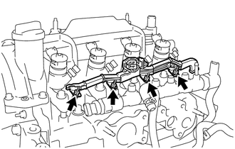
REMOVE FUEL INLET PIPE SUB-ASSEMBLY
-
Remove the bolt and No. 2 injection pipe clamp from the fuel inlet pipe sub-assembly and No. 4 injection pipe sub-assembly.
-
Using a union nut wrench 17 mm, loosen the 2 union nuts in the order shown in the illustration, and remove the fuel inlet pipe sub-assembly from the injector assembly and common rail assembly.
Note
To prevent contamination by foreign matter, after removing the fuel inlet pipe sub-assembly, protect the connecting portions of the injector assembly and common rail assembly with plastic bags.
-
-
REMOVE NO. 4 INJECTION PIPE SUB-ASSEMBLY
-
Using a union nut wrench 17 mm, loosen the 2 union nuts in the order shown in the illustration, and remove the No. 4 injection pipe sub-assembly from the injector assembly and common rail assembly.
Note
To prevent contamination by foreign matter, after removing the No. 4 injection pipe sub-assembly, protect the connecting portions of the injector assembly and common rail assembly with plastic bags.
-
-
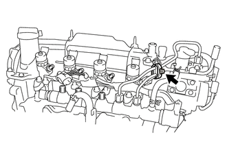
REMOVE NO. 2 FUEL HOSE
-
Slide the 2 hose clips and remove the No. 2 fuel hose from the No. 2 nozzle leakage pipe and common rail assembly.
-
-
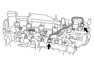
REMOVE NO. 1 FUEL HOSE
-
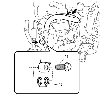
Text in Illustration *1 Union Bolt *2 Gasket Slide the hose clip and disconnect the No. 1 fuel hose from the No. 2 nozzle leakage pipe.
-
Remove the union bolt, No. 1 fuel hose and gasket from the supply pump assembly.
-
-
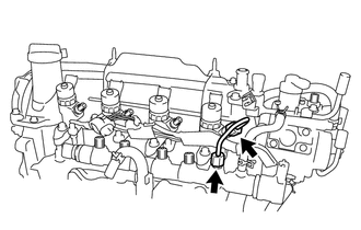
REMOVE NO. 2 NOZZLE LEAKAGE PIPE
-
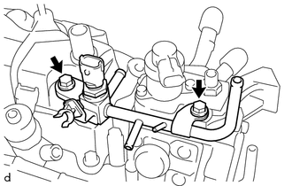
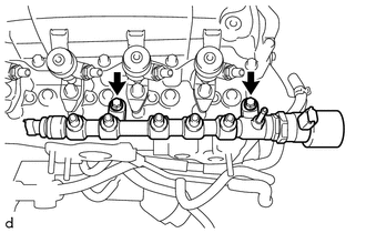
Remove the 2 bolts and No. 2 nozzle leakage pipe from the fuel pump protector and cylinder head cover sub-assembly.
-
-
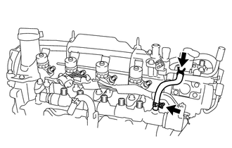
REMOVE FUEL PUMP PROTECTOR
-
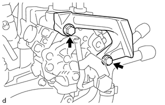
Remove the 2 bolts and fuel pump protector from the supply pump assembly.
Note
When the fuel pump protector fastening bolt has been loosened, tighten the supply pump assembly fastening bolt to the specified torque Click here.
-
-
REMOVE SUPPLY PUMP ASSEMBLY
-
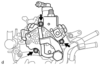
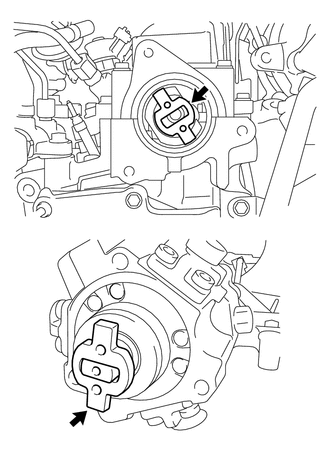
Remove the 3 bolts and supply pump assembly from the cylinder head sub-assembly and No. 3 camshaft bearing cap.
Note
If the supply pump drive coupling remains on the camshaft, remove the supply pump drive coupling from the camshaft.
-
-
REMOVE NO. 1 GLOW PLUG CONNECTOR
-
Remove the 4 glow plug screw grommets.
-
Remove the 4 nuts and No. 1 glow plug connector from each glow plug assembly.
-
-
REMOVE GLOW PLUG ASSEMBLY
-
Using a deep socket wrench 10 mm, remove the 4 glow plug assemblies from the cylinder head sub-assembly.
-
-
REMOVE COMMON RAIL ASSEMBLY
-
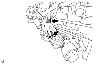
Disengage the hose clamp to separate the No. 4 water by-pass hose from the common rail assembly.
-
Slide the hose clip and remove the No. 4 water by-pass hose from the water inlet pipe.
-
Remove the 2 bolts and common rail assembly from the cylinder head sub-assembly.
-
-
REMOVE NO. 1 NOZZLE HOLDER CLAMP
-
REMOVE NOZZLE HOLDER CLAMP SEAT
-
REMOVE INJECTOR ASSEMBLY
-
REMOVE INJECTION NOZZLE SEAT
-
REMOVE OIL COOLER HOSE
-
Slide the 2 hose clips and remove the oil cooler hose from the water by-pass pipe sub-assembly and oil cooler assembly.
-
-
REMOVE NO. 2 OIL COOLER HOSE
-
Disengage the 4 clamps to separate the No. 2 oil cooler hose from the 2 clamps and water by-pass pipe sub-assembly.
-
Slide the hose clip and remove the No. 2 oil cooler hose from the oil filter bracket sub-assembly.
-
-
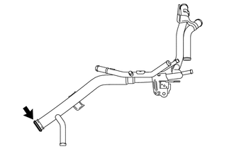
REMOVE NO. 3 WATER BY-PASS HOSE
-
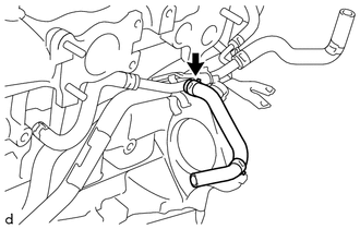
Slide the hose clip and remove the No. 3 water by-pass hose from the water by-pass pipe sub-assembly.
-
-
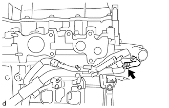
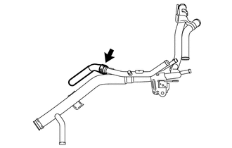
REMOVE NO. 2 WATER BY-PASS HOSE
-
Slide the hose clip and remove the No. 2 water by-pass hose from the water by-pass pipe sub-assembly.
-
-
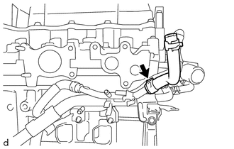
REMOVE NO. 1 TURBO WATER HOSE
-
Slide the hose clip and remove the No. 1 turbo water hose from the water by-pass pipe sub-assembly.
-
-
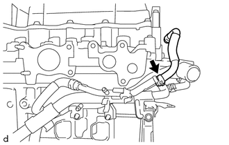
REMOVE NO. 2 TURBO WATER HOSE
-
Slide the hose clip and remove the No. 2 turbo water hose from the water by-pass pipe sub-assembly.
-
-
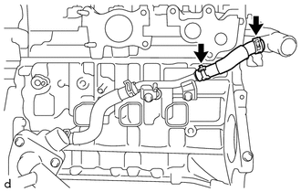
REMOVE NO. 6 WATER BY-PASS HOSE
-
Slide the 2 hose clips and remove the No. 6 water by-pass hose from the water by-pass pipe sub-assembly and water outlet sub-assembly.
-
-
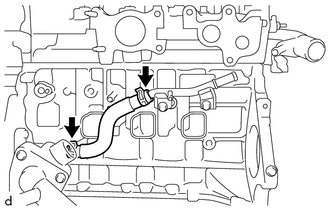
REMOVE WATER BY-PASS HOSE
-
Slide the hose clip and disconnect the water by-pass hose from the tube connector.
-
-
REMOVE WATER BY-PASS PIPE SUB-ASSEMBLY
-
Remove the 3 clamps from the water by-pass pipe sub-assembly.
-
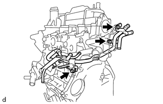
Remove the 3 bolts and water by-pass pipe sub-assembly from the No. 2 turbocharger stay, cylinder head sub-assembly, cylinder block sub-assembly and water inlet housing.
-
Slide the hose clip and remove the water by-pass hose from the water by-pass pipe sub-assembly.
-
Remove the water by-pass pipe O-ring from the water by-pass pipe sub-assembly.
-
-
REMOVE WATER INLET HOSE RH
-
Slide the 2 hose clips and remove the water inlet hose RH from the water outlet sub-assembly and water inlet pipe.
-
-
REMOVE WATER INLET HOSE LH
-
Slide the 2 hose clips and remove the water inlet hose LH from the water inlet pipe and water inlet housing.
-
-
REMOVE WATER INLET PIPE
-
Remove the 2 bolts and water inlet pipe from the cylinder block sub-assembly.
-
-
REMOVE VACUUM PUMP ASSEMBLY
-
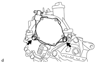
Remove the 2 bolts and vacuum pump assembly from the cylinder head sub-assembly.
-
Remove the 2 O-rings from the vacuum pump assembly.
-
-
REMOVE V-RIBBED BELT TENSIONER ASSEMBLY
-
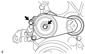
Remove the 2 bolts and V-ribbed belt tensioner assembly from the timing chain cover assembly.
-
-
REMOVE WIRING HARNESS CLAMP BRACKET
-
Remove the bolt and wiring harness clamp bracket from the timing chain cover assembly.
-
-
REMOVE NO. 2 TURBOCHARGER STAY
-
Remove the 2 bolts and No. 2 turbocharger stay from the cylinder head sub-assembly.
-
-
REMOVE OIL PAN COVER
-
Remove the 2 bolts, 2 plate washers and oil pan cover from the oil pan sub-assembly.
-
-
REMOVE NO. 2 OIL PAN COVER SILENCER
-
Remove the 2 bolts, 2 plate washers and No. 2 oil pan cover silencer from the oil pan sub-assembly.
-