CYLINDER BLOCK REPLACEMENT

PROCEDURE
-
REPLACE RING PIN
Note
It is not necessary to remove the ring pins unless they are being replaced.
-
Remove the 2 ring pins from the cylinder block sub-assembly.
-
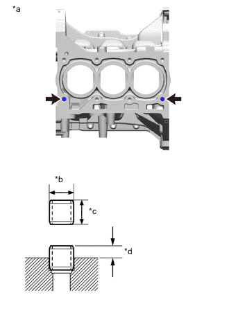
Text in Illustration *a Upper Side *b Width *c Height *d Protrusion Height Using a plastic hammer, tap in the 2 ring pins.
Standard Ring Pin Item Height Width Protrusion Height Ring Pin 11.7 to 12.3 mm (0.461 to 0.484 in.) 12.0 mm (0.472 in.) 6.0 to 7.0 mm (0.236 to 0.276 in.)
-
-
REPLACE STRAIGHT PIN
Note
It is not necessary to remove the straight pins unless they are being replaced.
-
Remove the 6 straight pins from the cylinder block sub-assembly.
-
Using a plastic hammer, tap in the 6 straight pins.
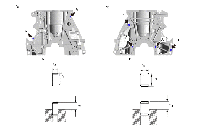
Text in Illustration *a Front Side *b Rear Side *c Width *d Height *e Protrusion Height - - Standard Straight Pin Item Height Width Protrusion Height Pin (A) 14.0 mm (0.551 in.) 6.0 mm (0.236 in.) 7.0 to 8.0 mm (0.276 to 0.315 in.) Pin (B) 15.0 mm (0.591 in.) 10.0 mm (0.394 in.) 8.0 to 9.0 mm (0.315 to 0.354 in.)
-
-
REPLACE OIL JET
Note
It is not necessary to remove the oil jet unless they are being replaced.
-
Remove the oil jet from the cylinder block sub-assembly.
-
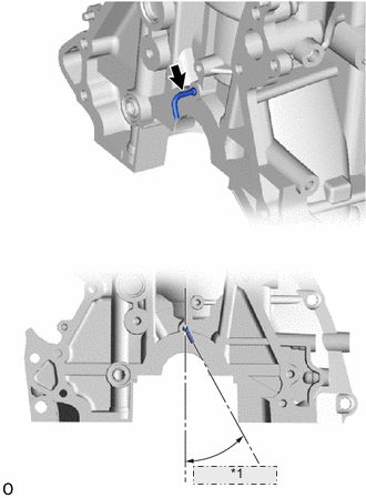
*1 23.5 to 33.5° Install the oil jet to the cylinder block sub-assembly as shown in the illustration.
Note
Do not tap the tip of the oil jet.
-