CYLINDER BLOCK DISASSEMBLY

PROCEDURE
-
INSPECT CONNECTING ROD THRUST CLEARANCE
-
INSPECT CONNECTING ROD OIL CLEARANCE
-
REMOVE PISTON SUB-ASSEMBLY WITH CONNECTING ROD SUB-ASSEMBLY
Note
Do not turn the crankshaft.
-
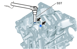
Using SST, remove the 2 connecting rod bolts from the connecting rod bearing cap.
- SST
- 09205-16011
Note
Arrange the removed parts in the correct order.
-
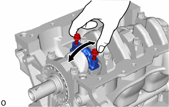
Using the 2 removed connecting rod bolts, remove the connecting rod bearing cap and connecting rod bearing by wiggling the connecting rod bearing cap back and forth.
Tech Tips
Keep the piston, connecting rod sub-assembly and connecting rod bearing cap together.
-
Push the piston, connecting rod sub-assembly and connecting rod bearing through the top of the cylinder block sub-assembly.
Note
Do not disassemble the piston, piston pin and connecting rod. If the piston pin is removed, the piston, piston pin and connecting rod cannot be reused.
Tech Tips
-
Keep the piston, connecting rod sub-assembly and connecting rod bearing cap together.
-
Arrange the removed parts in the correct order.
-
-
-
REMOVE CONNECTING ROD BEARING
-
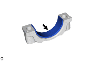
Remove the connecting rod bearing from the connecting rod sub-assembly.
Tech Tips
Arrange the removed parts in the correct order.
-
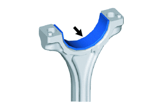
Remove the connecting rod bearing from the connecting rod bearing cap.
Tech Tips
Arrange the removed parts in the correct order.
-
-
REMOVE PISTON RING SET
-
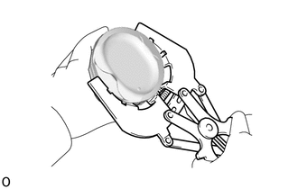
Using a piston ring expander, remove the No. 1 compression ring and No. 2 compression ring from the piston.
-
Remove the expander spacer and 2 side rails by hand.
Tech Tips
Arrange the removed parts in the correct order.
-
-
INSPECT CRANKSHAFT THRUST CLEARANCE
-
INSPECT CRANKSHAFT OIL CLEARANCE
-
REMOVE CRANKSHAFT
-
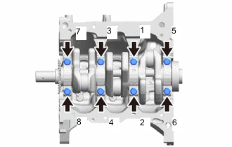
Remove the 8 crankshaft bearing cap set bolts from the crankshaft bearing cap in the order shown in the illustration.
Note
Loosen the crankshaft bearing cap set bolts in 2 or 3 steps in the order shown in the illustration.
-
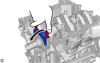
Using the removed crankshaft bearing cap set bolt, remove the 4 crankshaft bearing caps and 4 crankshaft bearings from the cylinder block sub-assembly.
Note
Arrange the removed parts in the correct order.
Tech Tips
-
If it is difficult to remove the crankshaft bearing cap, lightly tap it with a hammer.
-
Move the top of the crankshaft bearing cap back and forth in the axial direction.
-
-
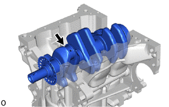
Remove the crankshaft from the cylinder block sub-assembly.
-
-
REMOVE CRANKSHAFT THRUST WASHER UPPER
-
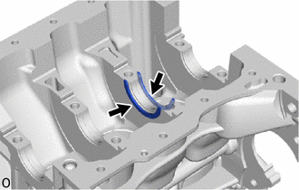
Remove the 2 crankshaft thrust washer uppers from the No. 3 journal position of the cylinder block sub-assembly.
-
-
REMOVE CRANKSHAFT BEARING
-
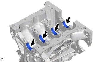
Remove the 4 crankshaft bearings from the cylinder block sub-assembly.
Tech Tips
Arrange the removed parts in the correct order.
-
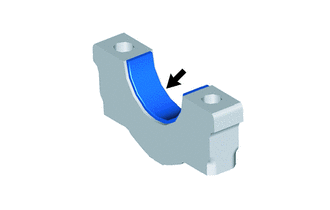
Remove the 4 crankshaft bearings from the 4 crankshaft bearing caps.
Tech Tips
Arrange the removed parts in the correct order.
-
-
REMOVE NO. 1 OIL NOZZLE SUB-ASSEMBLY
-
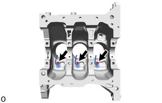
Using a 5 mm hexagon socket wrench, remove the 3 bolts and 3 No. 1 oil nozzle sub-assemblies from the cylinder block sub-assembly.
-