CYLINDER HEAD INSPECTION

PROCEDURE
-
INSPECT CYLINDER HEAD SUB-ASSEMBLY
-
Using a straightedge and feeler gauge, measure the warpage of the contact surface indicated in the illustration.
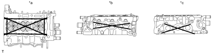
Text in Illustration *a Lower Side *b Intake Side *c Exhaust Side - - Maximum warpage 0.05 mm (0.002 in.) If the warpage is greater than the maximum, replace the cylinder head.
-
Using a dye penetrant, check the combustion chamber, intake ports, exhaust ports and cylinder block surface for cracks.
If cracked, replace the cylinder head.
-
-
INSPECT CAMSHAFT THRUST CLEARANCE
-
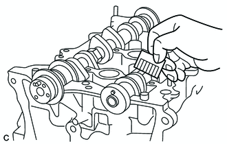
Install the 2 camshafts.
-
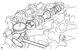
Using a dial indicator, measure the thrust clearance while moving the camshaft back and forth.
Standard thrust clearance 0.100 to 0.225 mm (0.00394 to 0.00886 in.) Maximum thrust clearance 0.240 mm (0.00944 in.) If the thrust clearance is greater than the maximum, replace the cylinder head. If damage is found on the camshaft thrust surfaces, replace the camshaft.
-
-
INSPECT CAMSHAFT OIL CLEARANCE
-
Clean the 7 bearing caps and camshaft journals.
-
Place the camshafts on the cylinder head.
-
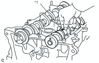
Text in Illustration *1 Plastigage Lay a strip of Plastigage on the journal in the axial direction.
-
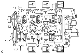
Text in Illustration *1 No. 1 Camshaft Bearing Cap *2 No. 2 Camshaft Bearing Cap Place the No. 1 camshaft bearing cap and No. 2 camshaft bearing caps and tighten the bolts to the specified torque in the order shown in the illustration.
- Torque:
- No. 1 camshaft bearing cap
- 15 N*m { 153 kgf*cm, 11 ft.*lbf }
- No. 2 camshaft bearing cap
- 13 N*m { 127 kgf*cm, 9 ft.*lbf }
-
Remove the 7 bearing caps.
-
Measure the Plastigage at its widest point.
Standard Oil Clearance Item Specified Condition (Intake Side) Specified Condition (Exhaust Side) Camshaft No. 1 journal 0.025 to 0.061 mm (0.00098 to 0.00240 in.) 0.037 to 0.073 mm (0.00146 to 0.00287 in.) Camshaft other journal 0.035 to 0.072 mm (0.00138 to 0.00283 in.) 0.035 to 0.072 mm (0.00138 to 0.00283 in.) Maximum Oil Clearance Item Specified Condition (Intake Side) Specified Condition (Exhaust Side) Camshaft No. 1 journal 0.09 mm (0.00354 in.) 0.10 mm (0.00393 in.) Camshaft other journal 0.10 mm (0.00393 in.) 0.10 mm (0.00393 in.) If the oil clearance is greater than the maximum, replace the camshaft.
If necessary, replace the cylinder head.
-
-
INSPECT INNER COMPRESSION SPRING
-
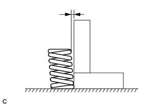
Using a steel square, measure the angle of the inner compression spring.
Maximum angle 2° If the angle is greater than the maximum, replace the inner compression spring.
-
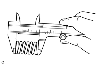
Using a vernier caliper, measure the free length of the inner compression spring.
Free length 51.63 mm (2.0327 in.) If the length is not as specified, replace the inner compression spring.
-
-
INSPECT INTAKE VALVE GUIDE BUSH OIL CLEARANCE
-
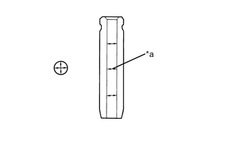
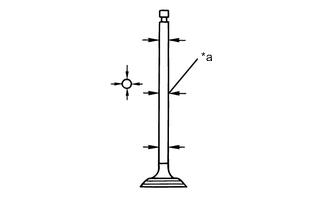
Text in Illustration *a Measuring Point Using a caliper gauge, measure the inside diameter of the guide bush.
Intake valve guide bush inside diameter 5.01 to 5.03 mm (0.19724 to 0.19803 in.) If the diameter is not as specified, check the oil clearance.
-
Text in Illustration *a Measuring Point Subtract the valve stem diameter measurement from the guide bush inside diameter measurement to calculate the oil clearance.
Intake valve stem diameter 4.970 to 4.985 mm (0.19567 to 0.19626 in.) Standard oil clearance 0.025 to 0.060 mm (0.00098 to 0.00236 in.) Maximum oil clearance 0.08 mm (0.00315 in.) If the clearance is greater than the maximum, replace the valve and valve guide bush.
-
-
INSPECT EXHAUST VALVE GUIDE BUSH OIL CLEARANCE
-
Text in Illustration *a Measuring Point Using a caliper gauge, measure the inside diameter of the guide bush.
Exhaust valve guide bush inside diameter 5.01 to 5.03 mm (0.19724 to 0.19803 in.) If the diameter is not as specified, check the oil clearance.
-
Text in Illustration *a Measuring Point Subtract the valve stem diameter measurement from the guide bush inside diameter measurement to calculate the oil clearance.
Exhaust valve stem diameter 4.965 to 4.980 mm (0.19547 to 0.19606 in.) Standard oil clearance 0.030 to 0.065 mm (0.00118 to 0.00256 in.) Maximum oil clearance 0.10 mm (0.00394 in.) If the clearance is greater than the maximum, replace the valve and valve guide bush.
-