ENGINE UNIT INSTALLATION

PROCEDURE
-
INSTALL WIRE HARNESS CLAMP BRACKET
-
Install the wire harness clamp bracket to the cylinder head cover sub-assembly with the bolt.
- Torque:
- 13 N*m { 127 kgf*cm, 9 ft.*lbf }
-
Install the wire harness clamp bracket to the timing chain cover sub-assembly with the bolt.
- Torque:
- 8.4 N*m { 86 kgf*cm, 74 in.*lbf }
-
-
INSTALL NO. 2 VENTILATION HOSE
-
Install the No. 2 ventilation hose to the cylinder head cover sub-assembly and slide the hose clip to secure it.
-
-
INSTALL VENTILATION HOSE
-
Install the ventilation hose to the ventilation valve sub-assembly and cylinder head cover sub-assembly and slide the 2 hose clips to secure it.
-
-
INSTALL V-RIBBED BELT TENSIONER ASSEMBLY
-
Install the V-ribbed belt tensioner assembly to the timing chain cover sub-assembly with the bolt.
- Torque:
- 54 N*m { 551 kgf*cm, 40 ft.*lbf }
-
-
INSTALL DUTY VACUUM SWITCHING VALVE
-
Install the duty vacuum switching valve to the cylinder head cover sub-assembly with the bolt.
- Torque:
- 8.8 N*m { 90 kgf*cm, 78 in.*lbf }
-
-
INSTALL FUEL INJECTOR ASSEMBLY
-
INSTALL FUEL PIPE INSULATOR
-
INSTALL INJECTOR VIBRATION INSULATOR
-
INSTALL FUEL DELIVERY PIPE
-
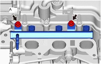
Temporarily install the fuel delivery pipe with fuel injector assembly to the cylinder head sub-assembly with the 2 bolts.
Note
-
Do not drop the fuel injector assembly.
-
After installing each fuel injector assembly, check that it turns smoothly. If not, replace the O-ring with a new one.
Tech Tips
Because bolt A interferes with the cylinder head cover sub-assembly, temporarily install it together with the fuel delivery pipe.
-
-
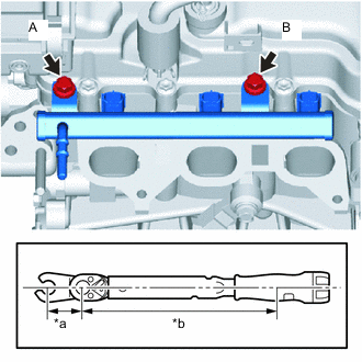
Text in Illustration *a Fulcrum Length of 12 mm Union Nut Wrench *b Fulcrum Length of Torque Wrench Using a 12 mm union nut wrench, fully tighten bolt A.
- Torque:
- Specified tightening torque
- 27 N*m { 275 kgf*cm, 20 ft.*lbf }
Tech Tips
-
Calculate the torque wrench reading when changing the fulcrum length of the torque wrench Click here.
-
When using a 12 mm union nut wrench (fulcrum length of 20 mm (0.79 in.)) + torque wrench (fulcrum length of 180 mm (7.09 in.)): 24 N*m (248 kgf*cm, 18 ft.*lbf).
-
Fully tighten bolt B.
- Torque:
- 27 N*m { 275 kgf*cm, 20 ft.*lbf }
-
-
INSTALL NO. 1 IGNITION COIL
-
INSTALL INLET EGR GASKET
-
INSTALL EXHAUST MANIFOLD TO HEAD GASKET
-
INSTALL EXHAUST MANIFOLD
-
INSTALL MANIFOLD STAY
-
INSTALL EGR VALVE GASKET
-
INSTALL EGR VALVE ASSEMBLY
-
Temporarily install the EGR valve assembly to the cylinder head sub-assembly.
-
-
INSTALL NO. 2 INTAKE MANIFOLD TO HEAD GASKET
-
INSTALL NO. 1 INTAKE MANIFOLD INSULATOR
-
INSTALL NO. 1 INTAKE MANIFOLD TO HEAD GASKET
-
INSTALL INTAKE MANIFOLD
-
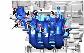
Temporarily install the intake manifold to the cylinder head sub-assembly with the 2 bolts and 2 nuts.
-
Fully tighten the 4 bolts and 3 nuts in the order shown in the illustration.
- Torque:
- 30 N*m { 306 kgf*cm, 22 ft.*lbf }
-
Connect the No. 2 fuel vapor feed hose to the duty vacuum switching valve and slide the hose clip to secure it.
-
-
INSTALL WIRE HARNESS CLAMP BRACKET
-
Install the wire harness clamp bracket to the cylinder head cover sub-assembly with the bolt.
- Torque:
- 8.4 N*m { 86 kgf*cm, 74 in.*lbf }
-
-
INSTALL FUEL TUBE SUB-ASSEMBLY
-
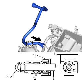
Text in Illustration *1 Retainer *2 O-ring *3 Fuel Tube Connector *4 Nylon Tube *5 Fuel Pipe 
Push Install the fuel tube sub-assembly to the fuel delivery pipe.
-
Align the fuel tube connector with the fuel pipe, and push them together until the fuel tube connector makes a "click" sound.
Tech Tips
If it is difficult to push the fuel pipe into the fuel tube connector, apply a small amount of clean engine oil to the tip of the fuel pipe and reinsert it.
-
After connecting the fuel lines, check that the fuel pipe and fuel tube connector are securely connected by pulling on them.
-
-
Engage the clamp to connect the fuel tube sub-assembly to the fuel hose clamp.
-
-
INSTALL EFI FUEL PIPE CLAMP
-
INSTALL THROTTLE BODY GASKET
-
INSTALL THROTTLE BODY WITH MOTOR ASSEMBLY
-
INSTALL AIR CLEANER CAP SUPPORT
-
INSTALL NO. 2 WATER BY-PASS HOSE
-
Install the No. 2 water by-pass hose to the cylinder head sub-assembly and slide the hose clip to secure it.
-
-
INSTALL INLET HEATER WATER HOSE A
-
Install the inlet heater water hose A to the cylinder head sub-assembly and slide the hose clip to secure it.
-
-
INSTALL NO. 2 WATER BY-PASS HOSE
-
Install the No. 2 water by-pass hose to the throttle body with motor assembly and EGR valve assembly and slide the 2 hose clips to secure it.
-
Engage the 2 clamps to connect the No. 2 water by-pass hose to the intake manifold.
-
-
INSTALL NO. 1 WATER BY-PASS HOSE
-
Install the No. 1 water by-pass hose to the throttle body with motor assembly and water by-pass hose and slide the 2 hose clips to secure it.
-
Engage the 3 clamps to connect the No. 1 water by-pass hose to the intake manifold and water by-pass hose clamp.
-