ENGINE UNIT INSTALLATION

PROCEDURE
-
INSTALL NO. 2 VENTILATION HOSE
-
Install the No. 2 ventilation hose to the cylinder head cover.
-
-
INSTALL FUEL INJECTOR ASSEMBLY
-
INSTALL FUEL DELIVERY PIPE
-
Install 3 new fuel injector vibration insulators to the cylinder head.
Note
Do not drop the fuel injectors when installing the fuel delivery pipe.
-
Provisionally install the 2 bolts which are used to hold the fuel delivery pipe to the cylinder head.
Note
Check that the fuel injector turns smoothly after installing it. If it does not, reinstall it with a new O-ring.
-
Tighten the 2 bolts which are used to hold the fuel delivery pipe to the cylinder head.
- Torque:
- 27 N*m { 275 kgf*cm, 20 ft.*lbf }
-
-
INSTALL EXHAUST MANIFOLD CONVERTER SUB-ASSEMBLY
-
INSTALL MANIFOLD STAY
-
INSTALL EGR INLET EXHAUST MANIFOLD PLATE
-
INSTALL NO. 1 IGNITION COIL
-
INSTALL ENGINE OIL LEVEL DIPSTICK GUIDE
-
Apply a small amount of engine oil to a new O-ring.
-
Install the O-ring to the engine oil level dipstick guide.
-
Install the engine oil level dipstick guide with the bolt.
- Torque:
- 10 N*m { 102 kgf*cm, 7 ft.*lbf }
-
-
INSTALL ENGINE OIL LEVEL DIPSTICK SUB-ASSEMBLY
-
TEMPORARILY INSTALL EGR VALVE ASSEMBLY
-
Install a new EGR valve gasket to the cylinder head.
-
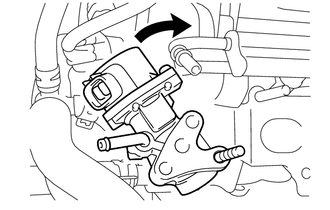
Insert the EGR valve into the stud bolt, rotate the EGR valve to avoid contact with the delivery pipe, and temporarily install the EGR valve.
-
-
TEMPORARILY INSTALL NO. 1 INTAKE MANIFOLD INSULATOR
-
INSTALL INTAKE MANIFOLD
-
Install a new No. 2 intake manifold to head gasket onto the intake manifold.
-
Temporarily install the intake manifold onto the No. 1 intake manifold insulator with the 2 bolts and 2 nuts.
-
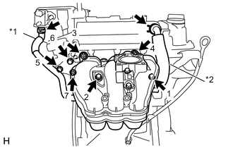
Text in Illustration *1 No. 2 Fuel Vapor Feed Hose *2 Ventilation Hose Tighten the 4 bolts and 3 nuts in the order shown in the illustration.
- Torque:
- 30 N*m { 306 kgf*cm, 22 ft.*lbf }
-
Connect the ventilation hose to the ventilation valve.
-
Connect the No. 2 fuel vapor feed hose to the duty vacuum switching valve.
-
Install the wire harness clamp bracket to the intake manifold with the bolt.
- Torque:
- 8.0 N*m { 85 kgf*cm, 73 in.*lbf }
-
-
INSTALL INTAKE MANIFOLD STAY
-
INSTALL FUEL TUBE SUB-ASSEMBLY
-
Install the fuel tube to the fuel pipe Click here.
-
Connect the fuel earth line to the cylinder head.
-
-
INSTALL EFI FUEL PIPE CLAMP
-
Install the EFI fuel pipe clamp to the fuel tube.
-
-
INSTALL THROTTLE WITH MOTOR BODY ASSEMBLY
-
INSTALL AIR CLEANER CAP SUPPORT
-
INSTALL WATER BY-PASS HOSE ASSEMBLY
-
Connect the 3 water by-pass hoses to the cylinder head and EGR valve.
-
Connect the 2 water by-pass hoses to the throttle body.
-
Engage the 2 water by-pass hoses to the hose clamps.
-
-
INSTALL AIR CLEANER FILTER ELEMENT SUB-ASSEMBLY
-
INSTALL AIR CLEANER CAP SUB-ASSEMBLY