ENGINE UNIT REASSEMBLY

PROCEDURE
-
INSTALL CYLINDER BLOCK WATER JACKET SPACER
-
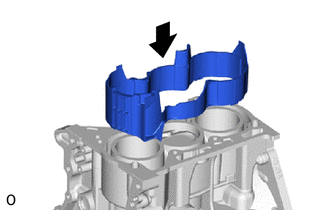
Install the cylinder block water jacket spacer to the cylinder block sub-assembly.
-
-
INSTALL CYLINDER HEAD GASKET
-
INSTALL CYLINDER HEAD SUB-ASSEMBLY
-
INSTALL VALVE LIFTER
-
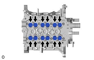
Apply engine oil to the circumference of the 12 valve lifters.
-
Install the 12 valve lifters to the cylinder head sub-assembly.
Note
Check that the valve lifters turn smoothly after installing them.
-
-
INSTALL ENGINE REAR OIL SEAL
-

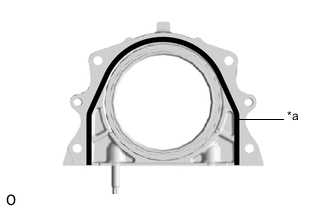
Apply engine oil to the lip of a new engine rear oil seal.
Text in Illustration 
Apply Engine Oil -
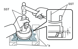
Text in Illustration *a Wooden Block Using SST and wooden blocks, tap in the engine rear oil seal to the rear engine oil seal retainer.
- SST
- 09223-15020
- 09950-70010 ( 09951-07200 )
Standard depth -0.5 to 1.0 mm (-0.0197 to 0.0394 in.) Note
-
Keep the lip free from foreign matter.
-
Do not tap in the engine rear oil seal at an angle.
-
-
INSTALL STUD BOLT
-
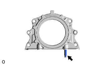
Using an E6 "TORX" socket wrench, install the stud bolt to the rear engine oil seal retainer.
- Torque:
- 5.0 N*m { 51 kgf*cm, 44 in.*lbf }
-
-
INSTALL REAR ENGINE OIL SEAL RETAINER
-
Clean and degrease the rear engine oil seal retainer and cylinder block sub-assembly.
-
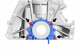
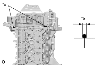
Text in Illustration *a Seal Packing (3.0 to 4.0 mm (0.118 to 0.157 in.)) Apply a continuous bead of seal packing to the rear engine oil seal retainer as shown in the illustration.
Seal packing Toyota Genuine Seal Packing Black, Three Bond 1207B or equivalent Note
-
Install the rear engine oil seal retainer within 3 minutes and tighten the bolts within 10 minutes of applying seal packing.
-
Do not add engine oil for at least 2 hours after installation.
-
Do not start the engine for at least 2 hours after installation.
-
-
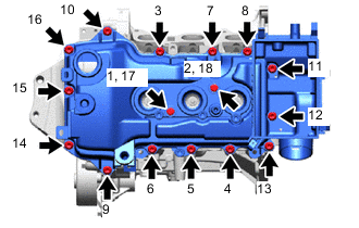
Install the rear engine oil seal retainer to the cylinder block sub-assembly with the 4 bolts.
- Torque:
- 10 N*m { 102 kgf*cm, 7 ft.*lbf }
-
-
INSTALL CAMSHAFT
-
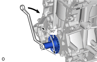
Before installing the camshaft, set the No. 1 piston to TDC/exhaust, and then turn the crankshaft approximately 90° clockwise so that a lifted valve and piston do not touch each other when the camshaft and No. 2 camshaft are installed.
-
Text in Illustration *a Apply Engine Oil Apply engine oil to the contact areas of the cams and journals of the camshaft and No. 2 camshaft.
-
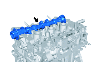
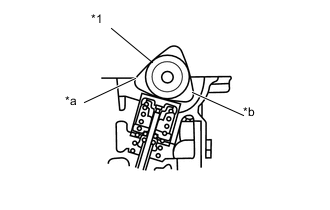
Install the camshaft to the cylinder head sub-assembly.
-
Text in Illustration *1 Camshaft *a No. 1 Cylinder *b No. 3 Cylinder Set the camshaft as shown in the illustration.
-
-
INSTALL NO. 2 CAMSHAFT
-
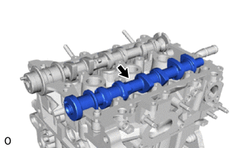
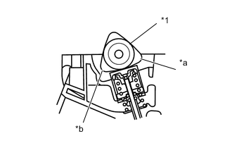
Install the No. 2 camshaft to the cylinder head sub-assembly.
-
Text in Illustration *1 No. 2 Camshaft *a No. 1 Cylinder *b No. 2 Cylinder Set the No. 2 camshaft as shown in the illustration.
-
-
INSTALL CAMSHAFT BEARING CAP
-
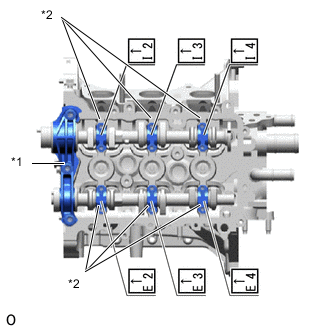
Text in Illustration *1 No. 1 Camshaft Bearing Cap *2 No. 2 Camshaft Bearing Cap Set the No. 1 camshaft bearing cap and No. 2 camshaft bearing caps.
Note
-
Install the camshaft bearing caps with the front marks facing the front of the engine.
-
Install the bolts to the correct positions by referring to the numbers inscribed on the bolts and the following table.
Installation Position of No. 2 Bearing Cap Installation Position Inscribed No. Intake No. 1 Cylinder I2 Intake No. 2 Cylinder I3 Intake No. 3 Cylinder I4 Exhaust No. 1 Cylinder E2 Exhaust No. 2 Cylinder E3 Exhaust No. 3 Cylinder E4 -
-
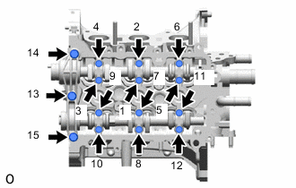
Install the 15 bolts in the order shown in the illustration.
- Torque:
- No. 1 Camshaft Bearing Cap
- 15 N*m { 153 kgf*cm, 11 ft.*lbf }
- No. 2 Camshaft Bearing Cap
- 13 N*m { 127 kgf*cm, 9 ft.*lbf }
-
-
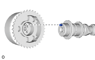
INSTALL CAMSHAFT TIMING GEAR
-
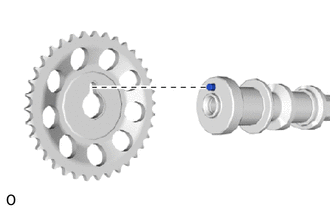
Fit the camshaft timing gear and No. 2 camshaft together by aligning the straight pin hole and straight pin.
-
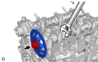
Text in Illustration *a Hold Using a wrench to hold the hexagonal portion of the No. 2 camshaft, tighten the bolt to install the camshaft timing gear to the No. 2 camshaft.
- Torque:
- 47 N*m { 479 kgf*cm, 35 ft.*lbf }
-
-
INSTALL CAMSHAFT TIMING SPROCKET ASSEMBLY
-
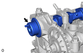
Apply engine oil to the camshaft timing sprocket assembly installation portion of the camshaft.
Text in Illustration 
Apply Engine Oil -
Fit the camshaft timing sprocket assembly and camshaft together by aligning the straight pin hole and straight pin.
Note
-
After insertion, gently rotate the camshaft timing sprocket assembly and check that the straight pin is securely inserted.
-
Because the tip of the camshaft straight pin may damage the seal surface of the camshaft timing sprocket assembly resulting in an improper seal, do not press forcefully on the camshaft timing sprocket assembly.
-
-
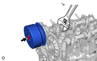
Text in Illustration *a Hold Using a wrench to hold the hexagonal portion of the camshaft, tighten the bolt to install the camshaft timing sprocket assembly to the camshaft.
- Torque:
- 47 N*m { 479 kgf*cm, 35 ft.*lbf }
-
-
INSTALL CRANKSHAFT STRAIGHT PIN
-
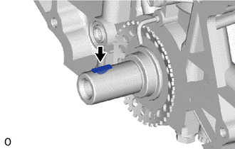
Install the crankshaft straight pin into the crankshaft groove.
-
-
INSTALL CRANKSHAFT TIMING GEAR OR SPROCKET
-
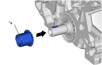
Text in Illustration *a Groove Align the groove of the crankshaft timing gear or sprocket with the straight pin of the crankshaft and install the crankshaft timing gear or sprocket to the crankshaft.
-
-
INSTALL TIMING CHAIN GUIDE
-
Install the timing chain guide to the cylinder head sub-assembly and cylinder block sub-assembly with the 2 bolts.
- Torque:
- 9.0 N*m { 92 kgf*cm, 80 in.*lbf }
-
-
INSTALL CHAIN SUB-ASSEMBLY
-
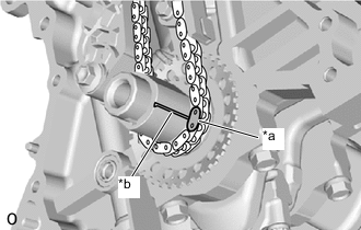
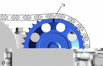
Text in Illustration *a Mark Plate (Yellow) *b Timing Mark Align the mark plate (yellow) with the timing mark of the crankshaft timing sprocket and install the chain sub-assembly as shown in the illustration.
-
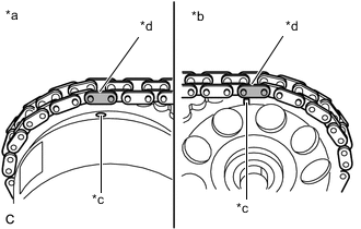
Text in Illustration *a Camshaft Timing Sprocket Assembly Side *b Camshaft Timing Gear Side *c Timing Mark *d Mark Plate (Orange) Align the 2 mark plates (orange) with the timing marks of the camshaft timing sprocket assembly and camshaft timing gear, and install the chain sub-assembly as shown in the illustration.
-
-
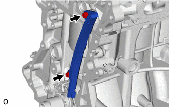
INSTALL TIMING CHAIN TENSION ARM
-
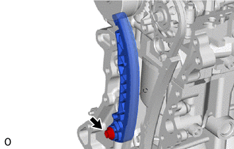
Install the timing chain tension arm to the cylinder block sub-assembly with the bolt.
- Torque:
- 19 N*m { 194 kgf*cm, 14 ft.*lbf }
-
-
INSTALL NO. 1 CHAIN TENSIONER ASSEMBLY
-
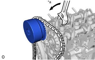
Text in Illustration *a Turn Using a wrench, slightly turn the hexagonal portion of the camshaft assembly (intake side) counterclockwise so that there is some slack in the chain sub-assembly on the No. 1 chain tensioner assembly side.
-
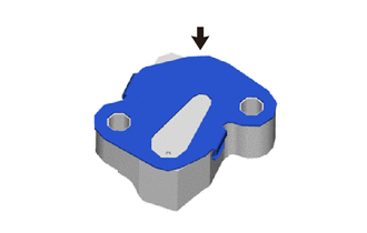
Install a new chain tensioner gasket to the No. 1 chain tensioner assembly.
-
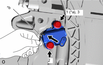
Text in Illustration *a Temporarily Tighten *b 3 mm Hexagon Wrench Install the No. 1 chain tensioner assembly with the chain tensioner gasket to the cylinder block sub-assembly with the 2 bolts in the order shown in the illustration.
- Torque:
- 11 N*m { 107 kgf*cm, 8 ft.*lbf }
-
Remove the 3 mm hexagon wrench, turn the crankshaft 2 complete revolutions and adjust the chain tension.
-
Text in Illustration *a Timing Mark Make sure that the timing mark of the camshaft timing gear is at the top with the chain sub-assembly tensioned (set No. 1 piston to TDC/ exhaust).
-
-
INSTALL TIMING CHAIN COVER OIL SEAL
-
INSTALL TIMING GEAR COVER TIGHT PLUG
-
INSTALL TIMING CHAIN COVER SUB-ASSEMBLY
-
INSTALL CRANKSHAFT PULLEY
-
INSTALL OIL FILTER SUB-ASSEMBLY
-
INSTALL THERMOSTAT
-
INSTALL WATER INLET
-
INSTALL OIL STRAINER SUB-ASSEMBLY
-
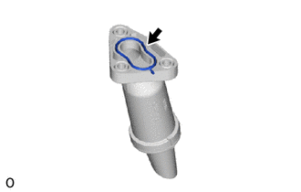
Install a new oil strainer gasket to the oil strainer sub-assembly.
-
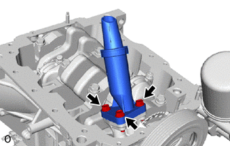
Install the oil strainer sub-assembly to the timing chain cover sub-assembly with the 3 bolts.
- Torque:
- 8.5 N*m { 87 kgf*cm, 75 in.*lbf }
-
-
INSTALL STRAIGHT PIN
Tech Tips
Perform this procedure only when replacement of the straight pin is necessary.
-
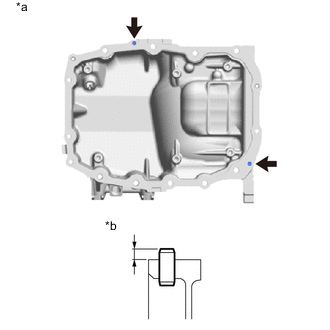
Text in Illustration *a Upper Side *b Protrusion Height Using a plastic hammer, tap in 2 new straight pins to the specified protrusion height.
Standard protrusion height 3.0 to 5.0 mm (0.118 to 0.197 in.)
-
-
INSTALL NO. 2 OIL PAN SUB-ASSEMBLY
-
Text in Illustration *a Hole Install the No. 2 oil pan sub-assembly to the oil pan sub-assembly with the 2 bolts.
Note
Make sure that the gasket around the hole of the No. 2 oil pan sub-assembly is not displaced of protruding.
- Torque:
- 10 N*m { 102 kgf*cm, 7 ft.*lbf }
-
-
INSTALL NO. 1 OIL PAN BAFFLE PLATE
-
Temporarily install the No. 1 oil pan baffle plate to the No. 2 oil pan sub-assembly with the 4 bolts.
-
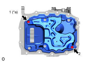
Text in Illustration *a Temporarily Tighten Tighten the 2 bolts in the order shown in the illustration.
- Torque:
- 10 N*m { 102 kgf*cm, 7 ft.*lbf }
-
Fully tighten the 3 bolts.
- Torque:
- 10 N*m { 102 kgf*cm, 7 ft.*lbf }
-
-
INSTALL OIL PAN SUB-ASSEMBLY
-
Remove any old seal packing remaining on the sealing surfaces before applying seal packing.
-
Clean the contact surfaces of the oil pan sub-assembly and cylinder block sub-assembly, and confirm that there is no oil, moisture or other foreign matter on the surfaces.
-
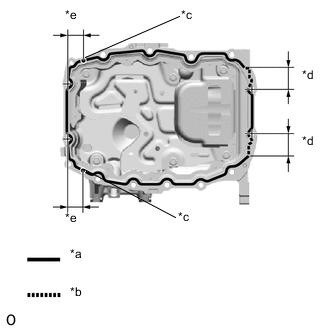
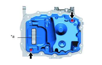
Text in Illustration *a Continuous Line Area (3.0 to 4.0 mm (0.118 to 0.157 in.)) *b Contact surfaces of the rear engine oil seal retainer and cylinder block sub-assembly (5.0 to 6.0 mm (0.197 to 0.236 in.)) *c Contact surfaces of the timing chain cover sub-assembly and cylinder block sub-assembly (5.0 to 6.0 mm (0.197 to 0.236 in.)) *d 39.5 mm (1.56 in.) *e 25.5 mm (1.00 in.) Apply seal packing to the oil pan sub-assembly as shown in the illustration.
Seal packing Toyota Genuine Seal Packing Black, Three Bond 1207B or equivalent Note
-
Apply seal packing to the contact surfaces between the timing chain cover sub-assembly and cylinder block sub-assembly, and between the rear engine oil seal retainer and cylinder block sub-assembly.
-
Install the oil pan sub-assembly within 3 minutes and tighten the bolts within 10 minutes of applying seal packing.
-
Do not expose the seal to engine oil for at least 2 hours after installation.
-
Do not start the engine for at least 2 hours after installation.
-
-
Temporarily install the oil pan sub-assembly to the cylinder block sub-assembly and timing chain cover sub-assembly with the 6 bolts.
-
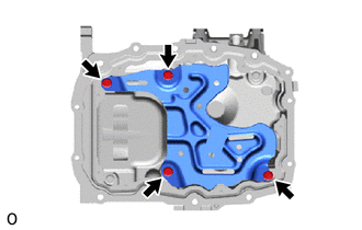
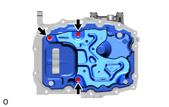
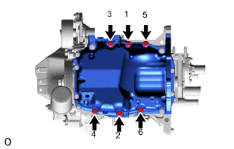
Fully tighten the 6 bolts in the order shown in the illustration.
- Torque:
- 24 N*m { 245 kgf*cm, 18 ft.*lbf }
-
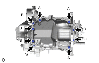
Text in Illustration *a Nut Install the 7 bolts and 2 nuts.
- Torque:
- Bolt A
- 24 N*m { 245 kgf*cm, 18 ft.*lbf }
- Bolt B, Nut
- 10 N*m { 102 kgf*cm, 7 ft.*lbf }
-
-
INSTALL OIL PAN DRAIN PLUG
-
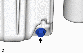
Install a new oil pan drain plug gasket and oil pan drain plug to the oil pan sub-assembly.
- Torque:
- 30 N*m { 301 kgf*cm, 22 ft.*lbf }
-
-
INSTALL GROMMET
-
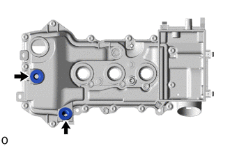
Install the 2 grommets to the cylinder head cover sub-assembly.
-
-
INSTALL VENTILATION SYSTEM GROMMET
-
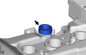
Install the ventilation system grommet to the cylinder head cover sub-assembly.
-
-
INSTALL PCV VALVE (VENTILATION VALVE SUB-ASSEMBLY)
-
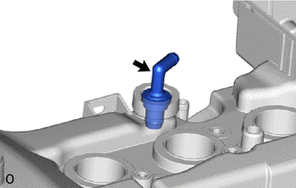
Install the PCV valve (ventilation valve sub-assembly) to the ventilation system grommet.
-
-
INSTALL CYLINDER HEAD COVER GASKET
-
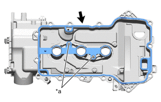
Text in Illustration *a Boss Install a new cylinder head cover gasket into the groove of the cylinder head cover sub-assembly and to the center bosses.
Note
Insert the cylinder head cover gasket securely into the bosses.
-
-
INSTALL CYLINDER HEAD COVER SUB-ASSEMBLY
-
Clean the cylinder head cover sub-assembly, cylinder head sub-assembly and timing chain cover sub-assembly.
-
Text in Illustration *a Seal Packing *b Diameter Apply a continuous bead of seal packing to the contact surface between the cylinder head sub-assembly and timing chain cover sub-assembly as shown in the illustration.
Seal packing Toyota Genuine Seal Packing Black, Three Bond 1207B or equivalent Standard diameter 3.0 to 4.0 mm (0.118 to 0.157 in.) Note
-
Install the timing chain cover sub-assembly within 3 minutes and tighten the bolts within 10 minutes of applying seal packing.
-
Do not expose the seal to engine oil for at least 2 hours after installation.
-
Do not start the engine for at least 2 hours after installation.
-
-
Temporarily install the cylinder head cover sub-assembly to the cylinder head sub-assembly and timing chain cover sub-assembly with the 16 bolts.
-
Fully tighten the 16 bolts in the order shown in the illustration.
- Torque:
- 7.7 N*m { 79 kgf*cm, 68 in.*lbf }
-
-
INSTALL OIL FILLER CAP SUB-ASSEMBLY
-
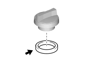
Install the oil filler cap gasket to the oil filler cap sub-assembly.
-
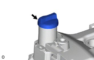
Install the oil filler cap sub-assembly to the cylinder head cover sub-assembly.
-
-
INSTALL OIL CONTROL VALVE FILTER
-
Text in Illustration *1 Oil Control Valve Filter *2 Cylinder Head Screw Plug Gasket *3 Head Taper Screw Plug Install the oil control valve filter to the head taper screw plug.
-
Using an 8 mm hexagon socket wrench, install a new cylinder head screw plug gasket and head taper screw plug with the oil control valve filter to the cylinder head sub-assembly.
- Torque:
- 25 N*m { 250 kgf*cm, 18 ft.*lbf }
-
-
INSTALL KNOCK SENSOR
-
Text in Illustration *a Top Install the knock sensor to the cylinder block sub-assembly with the bolt so that the knock sensor installation position is as shown in the illustration.
- Torque:
- 20 N*m { 204 kgf*cm, 15 ft.*lbf }
Note
-
If the knock sensor has been struck or dropped, replace it.
-
Make sure that the knock sensor is in the correct position.
-
-
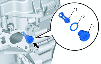
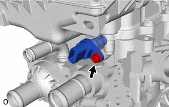
INSTALL ENGINE OIL PRESSURE SWITCH ASSEMBLY
-
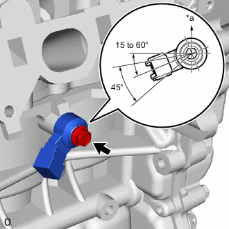
Text in Illustration *a Adhesive Clean and degrease the threads of the engine oil pressure switch assembly and threaded hole of the cylinder block sub-assembly.
-
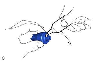
Apply adhesive to 2 or 3 threads of the engine oil pressure switch assembly.
Adhesive Toyota Genuine Adhesive 1344, Three Bond 1344 or equivalent Note
To prevent contamination by foreign matter, install immediately after applying adhesive.
-
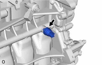
Using a 24 mm deep socket wrench, install the engine oil pressure switch assembly to the cylinder block sub-assembly.
- Torque:
- 15 N*m { 153 kgf*cm, 11 ft.*lbf }
Note
-
If the engine oil pressure switch assembly has been struck or dropped, replace it.
-
Do not start the engine for at least 1 hour after installation.
-
-
INSTALL CRANKSHAFT POSITION SENSOR
-
Apply a light coat of engine oil to the O-ring of the crankshaft position sensor.
Note
If reusing the crankshaft position sensor, be sure to inspect the O-ring.
-
Install the crankshaft position sensor to the timing chain cover sub-assembly with the bolt.
- Torque:
- 7.5 N*m { 76 kgf*cm, 66 in.*lbf }
Note
-
If the crankshaft position sensor has been struck or dropped, replace it.
-
Make sure that the O-ring is not cracked or does not move out of place during installation.
-
-
INSTALL CAM TIMING OIL CONTROL VALVE O-RING
-
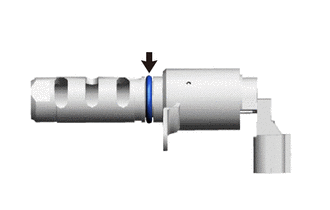
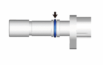
Apply a light coat of engine oil to a new cam timing oil control valve O-ring and install it to the camshaft timing oil control valve assembly.
-
-
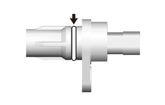
INSTALL CAMSHAFT TIMING OIL CONTROL VALVE ASSEMBLY
-
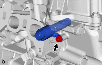
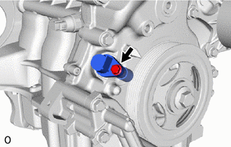
Install the camshaft timing oil control valve assembly to the cylinder head sub-assembly with the bolt.
- Torque:
- 10 N*m { 102 kgf*cm, 7 ft.*lbf }
Note
-
If the camshaft timing oil control valve assembly has been struck or dropped, replace it.
-
Do not allow foreign matter to contact the oil seal face of the camshaft timing oil control valve assembly (connecting surface with the cylinder head sub-assembly).
-
Make sure that the cam timing oil control valve O-ring is not cracked or does not move out of place during installation.
-
-
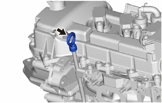
INSTALL ENGINE COOLANT TEMPERATURE SENSOR
-
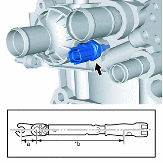
Text in Illustration *a Fulcrum Length of 19 mm Union Nut Wrench *b Fulcrum Length of Torque Wrench Using a 19 mm union nut wrench, install the engine coolant temperature sensor and a new gasket to the cylinder head sub-assembly.
- Torque:
- Specified tightening torque
- 20 N*m { 200 kgf*cm, 14 ft.*lbf }
Note
If the engine coolant temperature sensor has been struck or dropped, replace it.
Tech Tips
-
Calculate the torque wrench reading when changing the fulcrum length of the torque wrench Click here.
-
When using a 19 mm union nut wrench (fulcrum length of 30 mm (1.18 in.)) + torque wrench (fulcrum length of 180 mm (7.09 in.)): 17 N*m (173 kgf*cm, 13 ft.*lbf).
-
-
INSTALL CAMSHAFT POSITION SENSOR
-
Apply a light coat of engine oil to the O-ring of the camshaft position sensor.
Note
If reusing the camshaft position sensor, be sure to inspect the O-ring.
-
Install the camshaft position sensor to the cylinder head sub-assembly with the bolt.
- Torque:
- 7.5 N*m { 76 kgf*cm, 66 in.*lbf }
Note
-
If the camshaft position sensor has been struck or dropped, replace it.
-
Make sure that the O-ring is not cracked or does not move out of place during installation.
-
-
INSTALL SPARK PLUG
-
INSTALL OIL LEVEL DIPSTICK GUIDE O-RING
-
Apply a light coat of engine oil to the oil level dipstick guide O-ring.
-
Install the oil level dipstick guide O-ring to the oil level dipstick guide.
-
-
INSTALL OIL LEVEL DIPSTICK GUIDE
-
Install the oil level dipstick guide to the cylinder head sub-assembly and oil pan sub-assembly with the bolt.
- Torque:
- 10 N*m { 102 kgf*cm, 7 ft.*lbf }
-
-
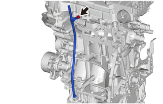
INSTALL OIL LEVEL DIPSTICK SUB-ASSEMBLY
-
Install the oil level dipstick sub-assembly to the oil level dipstick guide.
-
-
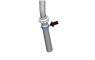
INSTALL WATER BY-PASS PIPE
-
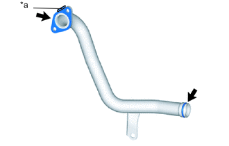
Text in Illustration *a Folded Tab Install 2 new water by-pass pipe gaskets to the water by-pass pipe as shown in the illustration.
Note
Install the water by-pass pipe gasket with its folded tab towards the water by-pass pipe.
Tech Tips
Apply water to the water by-pass pipe before installing the water by-pass gaskets to the water by-pass pipe.
-
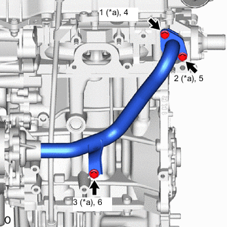
Text in Illustration *a Temporarily Tighten Install the water by-pass pipe to the cylinder head sub-assembly, cylinder block sub-assembly and timing chain cover sub-assembly with the 3 bolts in the order shown in the illustration.
- Torque:
- 24 N*m { 245 kgf*cm, 18 ft.*lbf }
-