ENGINE UNIT REASSEMBLY

PROCEDURE
-
INSTALL CYLINDER BLOCK WATER JACKET SPACER (w/ Cylinder Block Water Jacket Spacer)
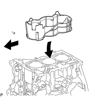
Text in Illustration *a Engine Front Side
-
Install the cylinder block water jacket spacer to the cylinder block.
-
-
INSTALL CYLINDER HEAD GASKET
-
INSTALL CYLINDER HEAD SUB-ASSEMBLY
Note
Place the cylinder head sub-assembly gently in order not to damage the cylinder head gasket.
-
Place the cylinder head on the cylinder block.
-
Install the 8 plate washers to the cylinder head sub-assembly.
Note
Do not drop the washers into the cylinder head sub-assembly.
-
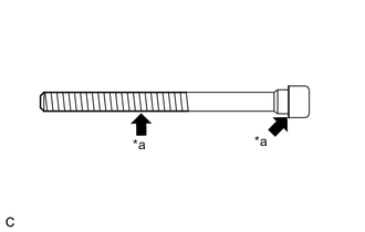
Text in Illustration *a Apply Engine Oil Apply engine oil to each cylinder head set bolt thread and seating surface.
-
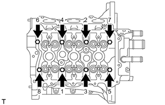
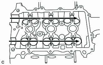
Using several passes, uniformly install and tighten the 8 cylinder head set bolts with an 8 mm bi-hexagon wrench in the order shown in the illustration.
- Torque:
- 32 N*m { 326 kgf*cm, 24 ft.*lbf }
-
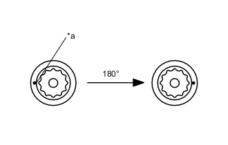
Text in Illustration *a Paint Mark Mark the front of each cylinder head set bolt with paint.
-
Retighten the cylinder head set bolts by additional 180° as shown in the illustration.
-
Check that the painted marks are now 180° from the front.
-
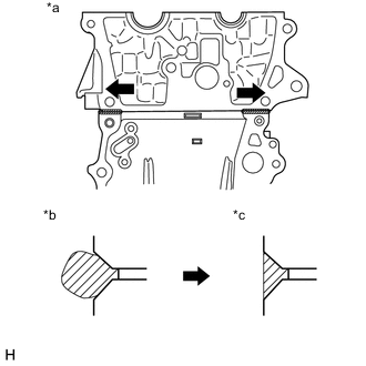
Text in Illustration *a Direction to wipe off *b Before wiping off *c After wiping off After tightening the cylinder head set bolts, wipe off the seal packing material that seeped out from the contact surface between the cylinder head sub-assembly and cylinder block.
Note
-
Be sure to wipe off the seal packing from inside to outside, parallel to the joint line.
-
Be sure to avoid clogging the bolt holes when wiping off the seal packing.
-
-
-
INSTALL VALVE LIFTER
-
Apply engine oil to the circumference of the valve lifters.
-
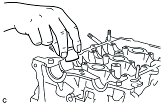
Install the valve lifters straight into the lifter holes.
Note
Check that the valve lifters turn smoothly after installing them.
-
-
INSTALL ENGINE REAR OIL SEAL
-
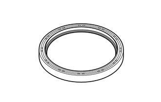
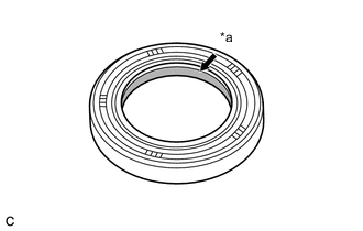
Apply engine oil to the lip of a new engine rear oil seal.
Text in Illustration 
Apply Engine Oil -
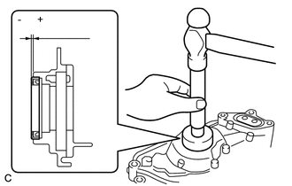
Using SST, tap the engine rear oil seal straight in.

Text in Illustration *1 Engine Rear Oil Seal Retainer *2 Wooden Block - SST
- 09223-15020
- 09950-70010 ( 09951-07200 )
Standard depth -1.0 to 0.5 mm (-0.0394 to 0.0197 in.) Note
-
Keep the lip free from foreign materials.
-
Do not tap on the engine rear oil seal at an angle.
-
-
INSTALL ENGINE REAR OIL SEAL RETAINER
-
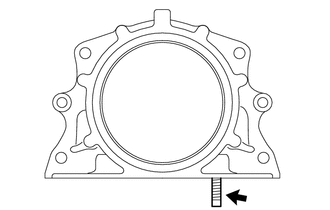
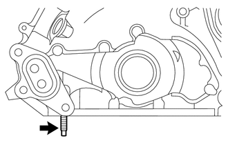
Install the stud bolt to the engine rear oil seal retainer.
-
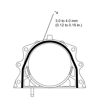
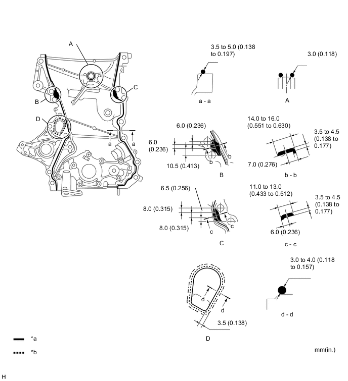
Text in Illustration *a Seal Packing Apply a continuous bead of seal packing as shown in the illustration.
Seal packing Toyota Genuine Seal Packing Black, Three Bond 1207B or equivalent -
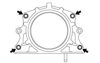
Install the engine rear oil seal retainer to the cylinder block with the 4 bolts.
- Torque:
- 10 N*m { 102 kgf*cm, 7 ft.*lbf }
Note
-
Install the engine rear oil seal retainer within 3 minutes and tighten the bolts within 15 minutes after applying seal packing.
-
Do not add engine oil for at least 2 hours after installation.
-
Do not start the engine for at least 2 hours after installation.
-
-
INSTALL VENTILATION BAFFLE PLATE
-
Clean the installation surface of the cylinder block and ventilation baffle plate.
-
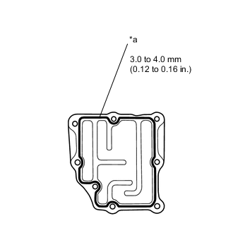
Text in Illustration *a Seal Packing Apply a continuous bead of seal packing as shown in the illustration.
Seal packing Toyota Genuine Seal Packing Black, Three Bond 1207B or equivalent -
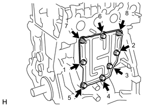
Install the ventilation baffle plate in the order shown in the illustration with the 6 bolts and 2 nuts.
- Torque:
- 24 N*m { 245 kgf*cm, 18 ft.*lbf }
Note
Install the ventilation baffle plate within 3 minutes and tighten the bolts within 15 minutes after applying seal packing.
-
-
INSTALL CAMSHAFTS
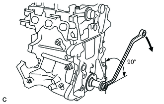
-
Before installing the camshaft, turn the crankshaft approximately 90° in the engine revolution direction from the point where the No. 1 piston is set at the TDC so that the lifted valve and piston do not touch each other.
-
Text in Illustration *a Apply Engine Oil Apply engine oil to the contact areas of the cam and journal of the camshaft and No. 2 camshaft.
-
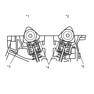
Text in Illustration *1 No. 1 Camshaft *2 No. 2 Camshaft *3 No. 3 Cylinder *4 No. 1 Cylinder *5 No. 2 Cylinder Install the camshafts as shown in the illustration.
-
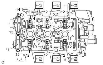
Text in Illustration *1 No. 1 Camshaft Bearing Cap *2 No. 2 Camshaft Bearing Cap Set the No. 1 camshaft bearing cap and No. 2 camshaft bearing caps and tighten the bolts in the order shown in the illustration.
- Torque:
- No. 1 Camshaft bearing cap
- 15 N*m { 153 kgf*cm, 11 ft.*lbf }
- No. 2 Camshaft bearing cap
- 13 N*m { 127 kgf*cm, 9 ft.*lbf }
Note
-
Install the bearing caps with the front marks facing the engine front.
-
Install the bolts in the correct positions by referring to the numbers inscribed on the bolts and the table below.
Installation position of the No. 2 bearing cap Installation position Inscribed No. Intake No. 1 cylinder I2 Intake No. 2 cylinder I3 Intake No. 3 cylinder I4 Exhaust No. 1 cylinder E2 Exhaust No. 2 cylinder E3 Exhaust No. 3 cylinder E4
-
-
INSTALL CAMSHAFT TIMING GEAR
-
Insert the camshaft timing gear so that the knock pin on the No. 2 camshaft end fits into the groove.
-
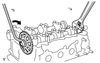
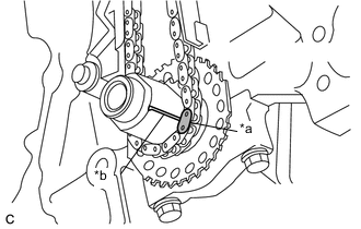
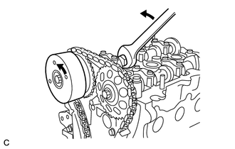
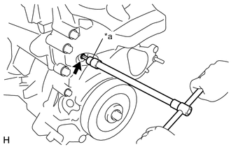
Text in Illustration *a Hold *b Turn While holding the hexagonal portion of the No. 2 camshaft, tighten the bolts to install the camshaft timing gear.
- Torque:
- 47 N*m { 479 kgf*cm, 35 ft.*lbf }
-
-
INSTALL CAMSHAFT TIMING SPROCKET ASSEMBLY
-
Apply engine oil to the camshaft timing sprocket assembly installation portion of the camshaft .
-
Insert the knock pin on the camshaft end into the knock hole in the camshaft timing sprocket assembly.
Note
-
Slightly turn the camshaft timing sprocket assembly to make sure that the knock pin is securely installed after inserting the knock pin.
-
The end surface of the camshaft timing sprocket assembly may be damaged if the camshaft timing sprocket assembly is turned with excessive force when the knock pin is not inserted.
-
-
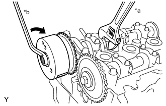
Text in Illustration *a Hold *b Turn While holding the hexagonal portion of the camshaft, tighten the bolts to install the camshaft timing sprocket assembly.
- Torque:
- 47 N*m { 479 kgf*cm, 35 ft.*lbf }
-
-
INSPECT VALVE CLEARANCE
-
ADJUST VALVE CLEARANCE
-
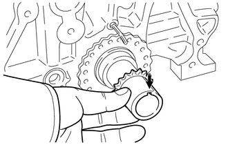
INSTALL CRANKSHAFT STRAIGHT PIN
-
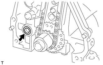
Install the crankshaft straight pin to the crankshaft groove.
-
-
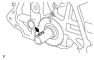
INSTALL CRANKSHAFT TIMING SPROCKET
-
Align the groove of the crankshaft timing sprocket with the key of the crankshaft and install the crankshaft timing sprocket.
-
-
INSTALL TIMING CHAIN GUIDE
-
Install the timing chain guide with the 2 bolts.
- Torque:
- 9.0 N*m { 92 kgf*cm, 80 in.*lbf }
-
-
INSTALL CHAIN SUB-ASSEMBLY
Text in Illustration *a Yellow Mark Plate *b Timing Mark
-
Align the yellow mark plate with the timing mark of the crankshaft timing sprocket and install the timing chain sub-assembly, as shown in the illustration.
-
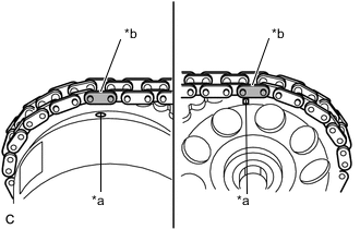
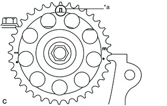
Text in Illustration *a Timing Mark *b Orange Mark Plate Align the 2 orange mark plates with the timing marks of the camshaft timing sprockets and install the timing chain sub-assembly, as shown in the illustration.
-
-
INSTALL TIMING CHAIN TENSION ARM
-
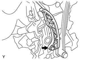
Install the timing chain tension arm with the bolt.
- Torque:
- 19 N*m { 194 kgf*cm, 14 ft.*lbf }
-
-
INSTALL NO. 1 CHAIN TENSIONER ASSEMBLY
-
Slightly turn the hexagonal portion of the camshaft assembly (intake side) counterclockwise to leave some slack on the chain of the No. 1 timing chain tensioner assembly side.
-
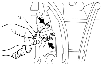
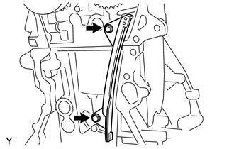
Text in Illustration *a Hexagon Wrench Install a new chain tensioner gasket and No. 1 chain tensioner assembly with the 2 bolts.
- Torque:
- 11 N*m { 107 kgf*cm, 8 ft.*lbf }
-
Remove the hexagon wrench, turn the crankshaft 2 complete revolutions and operate the chain tension.
-
Text in Illustration *a Timing Mark Make sure that the timing mark of the sprocket camshaft timing is at the top with the timing chain tensed (set No. 1 piston to the TDC/exhaust).
-
-
INSTALL TIMING CHAIN COVER OIL SEAL
-
Apply engine oil to the lip of a new timing chain cover oil seal.
Text in Illustration *a Engine oil -
Using SST, tap the timing chain cover oil seal straight in.
- SST
- 09950-60010 ( 09951-00500, 09952-06010 )
- 09950-70010 ( 09951-07200 )
Standard depth -1.0 to 0.5 mm (-0.0394 to 0.0197 in.) Note
Do not tap the timing chain cover oil seal at an angle.
-
-
INSTALL STUD BOLT (for TMC Made)
-
Apply adhesive to 2 or 3 threads (timing chain cover side) of the 2 stud bolts.
Adhesive Toyota Genuine Adhesive 1324, Three Bond 1344 or equivalent -

Install the 2 stud bolts to the timing chain cover sub-assembly.
-
-
INSTALL STUD BOLT (for TMMF Made)
-
Apply adhesive to 2 or 3 threads (timing chain cover side) of the stud bolt.
Adhesive Toyota Genuine Adhesive 1324, Three Bond 1344 or equivalent -
Install the stud bolt to the timing chain cover sub-assembly.
-
-
INSTALL TIMING CHAIN COVER SUB-ASSEMBLY
-
Remove any old packing material remaining on the sealing surfaces before applying seal packing.
-
Clean and degrease the contact surfaces of the timing chain cover sub-assembly, cylinder head sub-assembly, cylinder block and confirm that no oil, moisture, or other foreign matter remains on the surfaces.
-
Install a new oil pump gasket to the cylinder block.
-
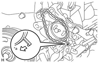
Apply seal packing to the timing chain cover sub-assembly as shown in the following illustration.
Text in Illustration *a Toyota Genuine Seal Packing Black, Three Bond 1207B *b Toyota Genuine Seal Packing 1282B, Three Bond 1282B Seal packing Water pump part Toyota Genuine Seal Packing 1282B, Three Bond 1282B or equivalent Other part Toyota Genuine Seal Packing Black, Three Bond 1207B or equivalent Note
-
Install the timing chain cover sub-assembly within 3 minutes and tighten the bolts within 10 minutes after applying seal packing.
-
Do not start the engine for at least 2 hours after installing.
-
-
Temporarily install the timing chain cover sub-assembly with the 11 bolts.
Bolt Length Item Length Bolt A 80 mm (3.150 in.) Bolt B 40 mm (1.575 in.) Bolt C
(with washer)
45 mm (1.772 in.) Bolt D 70 mm (2.756 in.) -
Install a new oil filter bracket gasket to the timing chain cover sub-assembly.
-
Temporarily install the oil filter bracket with the 3 bolts.
Bolt Length Item Length Bolt A 80 mm (3.150 in.) -
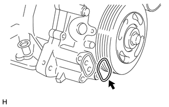
Text in Illustration *a Water Pump Side Install a new water pump gasket to the timing chain cover sub-assembly as shown in the illustration.
-
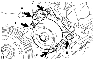
Temporarily install the engine water pump assembly with the 5 bolts.
Bolt Length Item Length Bolt E 20 mm (0.787 in.) Bolt F 50 mm (1.969 in.) Bolt G 45 mm (1.772 in.) -
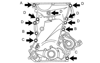
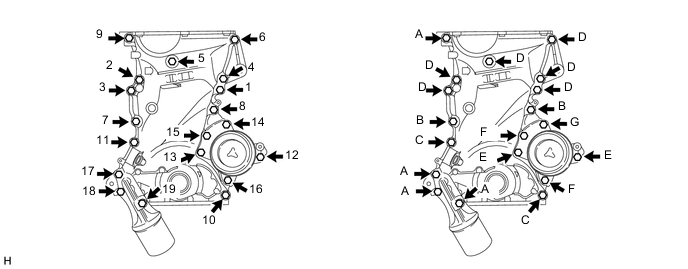
Fully tighten the timing chain cover sub-assembly with the 19 bolts in the order shown in the illustration.
- Torque:
- Bolt A, C
- 24 N*m { 245 kgf*cm, 18 ft.*lbf }
- Bolt B, D
- 40 N*m { 408 kgf*cm, 30 ft.*lbf }
- Bolt E, F, G
- 28 N*m { 286 kgf*cm, 21 ft.*lbf }
Bolt Length Item Length Bolt A 80 mm (3.150 in.) Bolt B 40 mm (1.575 in.) Bolt C
(with washer)
45 mm (1.772 in.) Bolt D 70 mm (2.756 in.) Bolt E 20 mm (0.787 in.) Bolt F 50 mm (1.969 in.) Bolt G 45 mm (1.772 in.) -
Wipe off the excess seal packing.
-
-
INSTALL DRAIN PLUG
-
Install the drain plug with a new gasket.
- Torque:
- 54 N*m { 551 kgf*cm, 40 ft.*lbf }
-
-
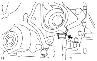
INSTALL TIGHT PLUG
Text in Illustration *a Adhesive
-
Clean the plug and the bolt holes of the timing chain cover sub-assembly and apply adhesive to the threads of the tight plug.
Adhesive Toyota Genuine Adhesive 1324, Three Bond 1324 or equivalent -
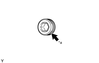
Text in Illustration *a 8 mm Socket Hexagon Wrench Using an 8 mm socket hexagon wrench, install the tight plug.
- Torque:
- 15 N*m { 153 kgf*cm, 11 ft.*lbf }
Note
Do not start the engine for at least 1 hour after installing.
-
-
INSTALL CRANKSHAFT PULLEY
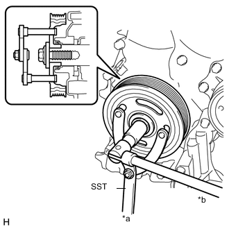
Text in Illustration *a Hold *b Turn
-
Align the pulley set key with the key groove of the crankshaft pulley, and then slide on the crankshaft pulley.
-
Using SST, install the crankshaft pulley bolt.
- SST
- 09960-10010 ( 09962-01000, 09963-01000 )
- Torque:
- 180 N*m { 1835 kgf*cm, 133 ft.*lbf }
-
-
INSTALL OIL FILTER SUB-ASSEMBLY
-
Check and clean the oil filter sub-assembly installation surface.
-
Apply clean engine oil to the gasket of a new oil filter.
-
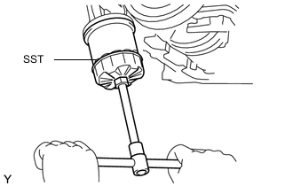
Gently screw the oil filter sub-assembly into place, then tighten it until the gasket comes into contact with the seat.
-
Using SST, tighten the oil filter sub-assembly.
- SST
- 09228-06501
- Torque:
- 10 N*m { 102 kgf*cm, 7 ft.*lbf }
-
-
CONNECT WATER BY-PASS HOSE
-
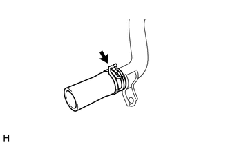
Connect the water by-pass hose to the No. 1 water by-pass pipe and slide the hose clip to secure it.
-
-
CONNECT NO. 1 WATER BY-PASS PIPE
-
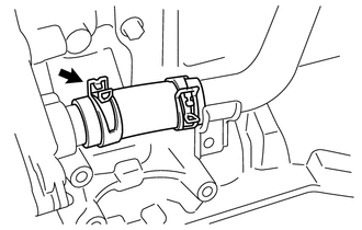
Connect the water by-pass hose with No. 1 water by-pass pipe to the timing chain cover sub-assembly and slide the hose clip to secure it.
-
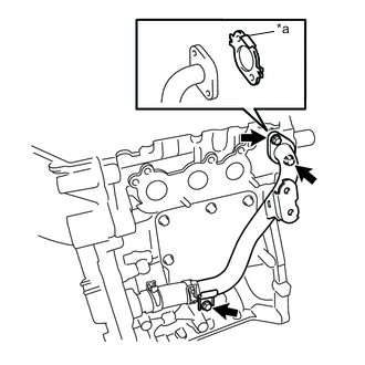
Text in Illustration *a Folded Tab Install a new water by-pass pipe gasket and No. 1 water by-pass pipe to the cylinder head sub-assembly and cylinder block with the 3 bolts.
- Torque:
- 24 N*m { 245 kgf*cm, 18 ft.*lbf }
Note
Install the water by-pass pipe gasket with its folded tab towards the No. 1 water by-pass pipe.
-
-
INSTALL THERMOSTAT
-
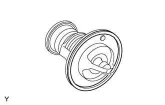
Install a new water outlet gasket to the thermostat.
-
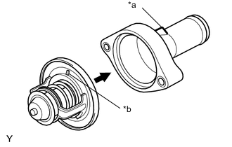
Text in Illustration *a Upper Indication *b Jiggle Pin Install the thermostat to the water inlet with the jiggle pin facing straight upward.
-
-
INSTALL WATER INLET
-
Install the water inlet with the 2 bolts.
- Torque:
- 7.0 N*m { 71 kgf*cm, 62 in.*lbf }
Note
-
Avoid catching the rubber gasket of thermostat under the water inlet.
-
Do not use a water inlet that has been dropped.
-
Ensure that gasket is secured between the water inlet and cylinder block.
-
-
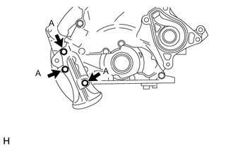
INSTALL OIL STRAINER SUB-ASSEMBLY
-
Install a new oil strainer gasket to the oil strainer sub-assembly.
-
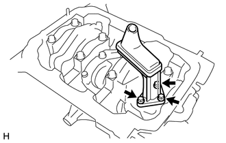
Install the oil strainer sub-assembly to the timing chain cover sub-assembly with the 3 bolts.
- Torque:
- 8.5 N*m { 87 kgf*cm, 75 in.*lbf }
-
-
INSTALL OIL PAN SUB-ASSEMBLY (for TMC Made)
-
Remove any old packing material remaining on the sealing surfaces before applying seal packing.
-
Clean and degrease the contact surfaces of the oil pan sub-assembly, cylinder block and confirm that no oil, moisture, or other foreign matter remains on the surfaces.
-
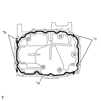
Text in Illustration *a Toyota Genuine Seal Packing Black, Three Bond 1207B *b Contact surface between timing chain cover and cylinder block *c Contact surface between oil seal retainer and cylinder block Apply seal packing to the oil pan sub-assembly as shown in the following illustration.
Seal packing Toyota Genuine Seal Packing Black, Three Bond 1207B or equivalent Note
-
Start and finish applying the seal packing on the seal surface with the cylinder block.
-
Apply seal packing to the contact surfaces between the timing chain cover sub-assembly and cylinder block, and between the engine rear oil seal retainer and cylinder block.
-
Install the oil pan sub-assembly within 3 minutes and tighten the bolts within 15 minutes of applying seal packing.
-
-
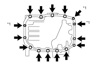
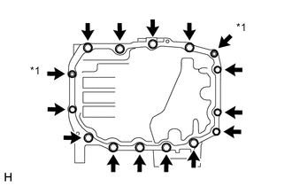
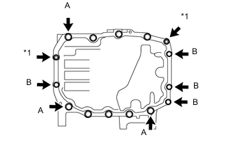
Text in Illustration *1 Nut Temporarily install the oil pan sub-assembly with the 12 bolts and 3 nuts.
-
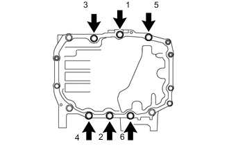
Fully tighten the 6 bolts in the order shown in the illustration.
- Torque:
- 24 N*m { 245 kgf*cm, 18 ft.*lbf }
-
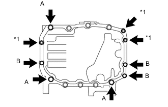
Text in Illustration *1 Nut Fully tighten the 6 bolts and 3 nuts.
- Torque:
- Bolt A
- 24 N*m { 245 kgf*cm, 18 ft.*lbf }
- Bolt B, Nut
- 10 N*m { 102 kgf*cm, 7 ft.*lbf }
-
-
INSTALL OIL PAN SUB-ASSEMBLY (for TMMF Made)
-
Remove any old packing material remaining on the sealing surfaces before applying seal packing.
-
Clean and degrease the contact surfaces of the oil pan sub-assembly, cylinder block and confirm that no oil, moisture, or other foreign matter remains on the surfaces.
-
Text in Illustration *a Toyota Genuine Seal Packing Black, Three Bond 1207B *b Contact surface between timing chain cover and cylinder block *c Contact surface between oil seal retainer and cylinder block Apply seal packing to the oil pan sub-assembly as shown in the following illustration.
Seal packing Toyota Genuine Seal Packing Black, Three Bond 1207B or equivalent Note
-
Start and finish applying the seal packing on the seal surface with the cylinder block.
-
Apply seal packing to the contact surfaces between the timing chain cover sub-assembly and cylinder block, and between the engine rear oil seal retainer and cylinder block.
-
Install the oil pan sub-assembly within 3 minutes and tighten the bolts within 15 minutes of applying seal packing.
-
-
Text in Illustration *1 Nut Temporarily install the oil pan sub-assembly with the 13 bolts and 2 nuts.
-
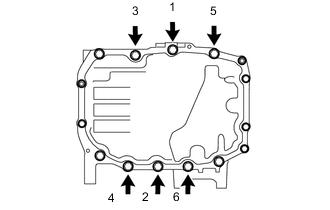
Fully tighten the 6 bolts in the order shown in the illustration.
- Torque:
- 24 N*m { 245 kgf*cm, 18 ft.*lbf }
-
Text in Illustration *1 Nut Fully tighten the 7 bolts and 2 nuts.
- Torque:
- Bolt A
- 24 N*m { 245 kgf*cm, 18 ft.*lbf }
- Bolt B, Nut
- 10 N*m { 102 kgf*cm, 7 ft.*lbf }
-
-
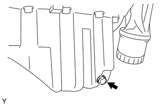
INSTALL OIL PAN DRAIN PLUG
-
Install the oil pan drain plug with a new oil pan drain plug gasket.
- Torque:
- 30 N*m { 301 kgf*cm, 22 ft.*lbf }
-
-
INSTALL VENTILATION VALVE SUB-ASSEMBLY
Text in Illustration *1 Ventilation Valve Sub-assembly *2 Grommet
-
Install a new grommet, as shown in the illustration.
-
Install the ventilation valve sub-assembly.
-
-
INSTALL CYLINDER HEAD COVER SUB-ASSEMBLY
-
Clean the cylinder head cover sub-assembly, cylinder head sub-assembly and timing chain cover sub-assembly.
-
Install a new cylinder head cover gasket into the groove on the cylinder head cover sub-assembly and onto the center bosses.
Note
Insert the gasket securely until it completely fits into the bosses.
-
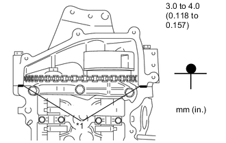
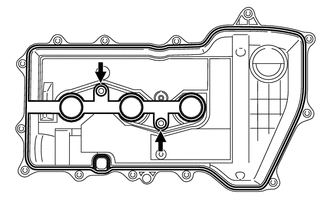
Text in Illustration *1 Seal Packing Apply a continuous bead of seal packing to the contact surface between the cylinder head sub-assembly and timing chain cover sub-assembly, as shown in the illustration.
Seal packing Toyota Genuine Seal Packing Black, Three Bond 1207B or equivalent Note
Install the timing chain cover sub-assembly within 3 minutes and tighten the bolts within 15 minutes after applying seal packing.
-
Temporarily install the cylinder head cover sub-assembly with the 13 bolts and 2 nuts.
-
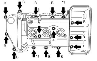
Text in Illustration *1 Nut Fully tighten the 2 bolts A, then fully tighten the 2 nuts, then fully tighten the 11 bolts B.
- Torque:
- 7.7 N*m { 79 kgf*cm, 68 in.*lbf }
-
-
INSTALL OIL FILLER CAP SUB-ASSEMBLY
-
Install a new oil filler cap gasket to the oil filler cap sub-assembly.
-
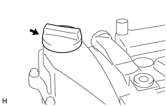
Install the oil filler cap sub-assembly.
-
-
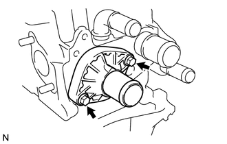
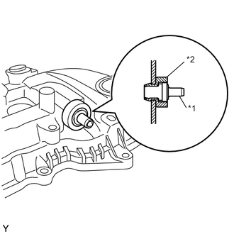
INSTALL OIL CONTROL VALVE FILTER
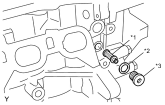
Text in Illustration *1 Oil Control Valve Filter *2 Gasket *3 Head Taper Screw Plug
-
Install the oil control valve filter onto the tight plug.
-
Text in Illustration *a 8 mm Hexagon Wrench Install a new gasket and install the oil control valve filter using an 8 mm hexagon wrench.
- Torque:
- 25 N*m { 250 kgf*cm, 18 ft.*lbf }
-
-
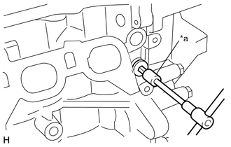
INSTALL ENGINE OIL PRESSURE SWITCH ASSEMBLY
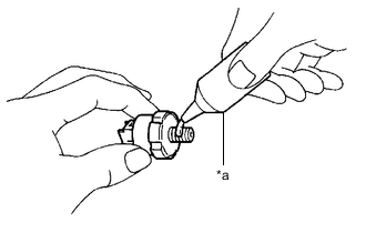
Text in Illustration *a Adhesive
-
Apply adhesive to 2 or 3 threads of the engine oil pressure switch assembly.
Adhesive Toyota Genuine Adhesive 1324, Three Bond 1324 or equivalent. -
Text in Illustration *a 24 mm Deep Socket Wrench Using a 24 mm deep socket wrench, install the engine oil pressure switch assembly.
- Torque:
- 15 N*m { 153 kgf*cm, 11 ft.*lbf }
Note
Do not start the engine for at least 1 hour after installation.
-
-
INSTALL KNOCK SENSOR
-
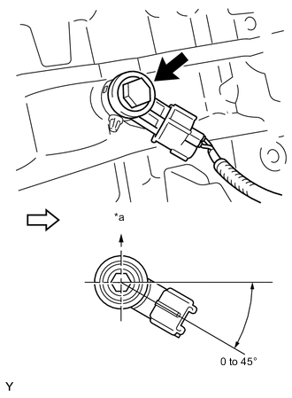
Text in Illustration *a Upper 
Front of Engine Install the knock sensor with the bolt as shown in the illustration.
- Torque:
- 20 N*m { 204 kgf*cm, 15 ft.*lbf }
Note
-
If a component has been dropped or subjected to a strong impact, replace it.
-
Make sure that each knock sensor is in the correct position.
-
-
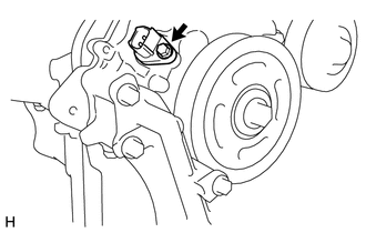
INSTALL CRANKSHAFT POSITION SENSOR
-
Apply a light coat of engine oil to the O-ring.
Note
If reusing the crankshaft position sensor, be sure to inspect the O-ring.
-
Install the crankshaft position sensor with the bolt.
- Torque:
- 7.5 N*m { 76 kgf*cm, 66 in.*lbf }
Note
-
If a component has been dropped or subjected to a strong impact, replace it.
-
Make sure that the O-ring is not damaged or does not jump out of position during installation.
-
-
INSTALL CAMSHAFT TIMING OIL CONTROL VALVE ASSEMBLY
-
Apply a light coat of engine oil to the O-ring.
Note
If reusing the camshaft timing oil control valve assembly, be sure to inspect the O-ring.
-
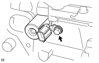
Install the camshaft timing oil control valve assembly with the bolt.
- Torque:
- 10 N*m { 102 kgf*cm, 7 ft.*lbf }
Note
-
If a component has been dropped or subjected to a strong impact, replace it.
-
Make sure that the O-ring is not damaged or does not jump out of position during installation.
-
-
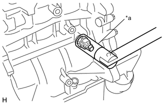
INSTALL ENGINE COOLANT TEMPERATURE SENSOR
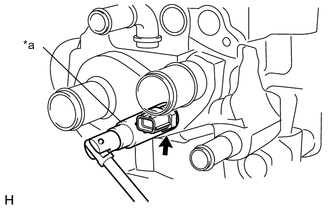
Text in Illustration *a 19 mm Deep Socket Wrench
-
Install a new gasket to the engine coolant temperature sensor.
-
Using a 19 mm deep socket wrench, install the engine coolant temperature sensor.
- Torque:
- 20 N*m { 200 kgf*cm, 14 ft.*lbf }
-
-
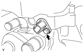
INSTALL CAMSHAFT POSITION SENSOR
-
Apply a light coat of engine oil to the O-ring.
Note
If reusing the camshaft position sensor, be sure to inspect the O-ring.
-
Install the camshaft position sensor with the bolt.
- Torque:
- 7.5 N*m { 76 kgf*cm, 66 in.*lbf }
Note
-
If a component has been dropped or subjected to a strong impact, replace it.
-
Make sure that the O-ring is not damaged or does not jump out of position during installation.
-
-
INSTALL SPARK PLUG