ENGINE UNIT INSPECTION

PROCEDURE
-
INSPECT CAMSHAFT TIMING SPROCKET ASSEMBLY
-
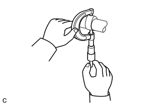
Temporarily install camshaft timing sprocket to the camshaft with the bolt.
-
Check the camshaft timing camshaft timing sprocket assembly lock.
-
Make sure that the camshaft timing sprocket assembly is locked.
-
-
Release the lock pin.
-
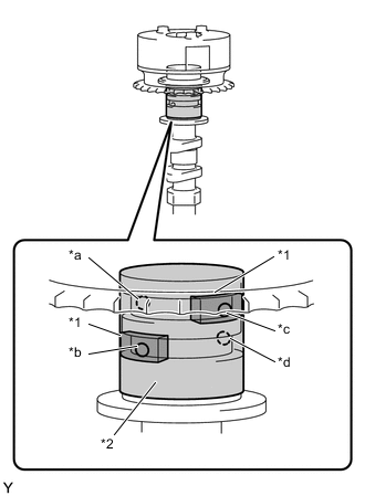
Text in Illustration *1 Rubber *2 Vinyl Tape *a Retard Side Path (Open) *b Advance Side Path (Close) *c Retard Side Path (Close) *d Advance Side Path (Open) Cover the 4 oil paths of the cam journal with vinyl tape as shown in the illustration.
Tech Tips
4 oil paths are provided in the groove. Plug 2 paths with rubber pieces.
-
Prick a hole in the tape placed on the advance side path. Prick a hole in the tape placed on the retard side path, on the opposite side to that of the advance side path, as shown in the illustration.
-
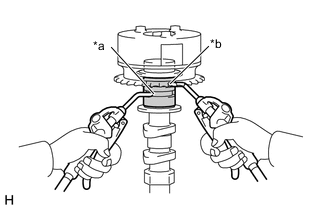
Text in Illustration *a Advance Side Path *b Retard Side Path Apply approximately 200 kPa (2.0 kgf/cm2, 28 psi) of air pressure to the 2 paths (the advance side path and the retard side path).
Note
Cover the paths with a piece of cloth when applying pressure to keep oil from splashing.
-
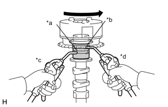
Text in Illustration *a Advance Side Path *b Retard Side Path *c Decompress *d Hold Pressure Make sure that the camshaft timing sprocket turns in the retard direction when reducing the air pressure applied to the advance side path.
Tech Tips
The lock pin is released and the camshaft timing sprocket turns in the retard direction.
-
When the camshaft timing sprocket moves to the most retarded position, release the air pressure from the advance side path, and then release the air pressure from the retard side path.
Note
Be sure to release the air pressure from the advance side path first. If the air pressure of the retard side path is released first, the camshaft timing sprocket may abruptly shift in the advance direction and break the lock pin or other parts.
-
-
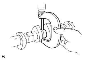
Check for smooth rotation.
-
Turn the camshaft timing sprocket within its movable range (25°) 2 or 3 times, but do not turn it to the most retarded position. Make sure that the sprocket turns smoothly.
Note
Perform this check by hand, instead of using air pressure.
-
-
Check the lock in the most retarded position.
-
Confirm that the camshaft timing sprocket is locked in the most retarded position.
-
-
-
INSPECT CAMSHAFT
-
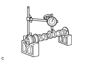
Inspect the camshaft for runout.
-
Using V-blocks and a dial indicator, measure the runout of the 3rd journal.
Maximum circle runout 0.03 mm (0.0012 in.) Tech Tips
The runout is the half of the value on the indicator when the camshaft is turned 1 revolution.
If the circle runout is greater than the maximum, replace the camshaft.
-
-
Inspect the cam lobes.
-
Using a micrometer, measure the cam lobe height.
Standard Cam Lobe Height Item Specification Camshaft 41.54 to 41.64 mm (1.6354 to 1.6394 in.) No. 2 Camshaft 40.97 to 41.07 mm (1.6310 to 1.6169 in.) Minimum Cam Lobe Height Item Specification Camshaft 41.44 mm (1.6315 in.) No. 2 Camshaft 40.87 mm (1.6091 in.) If the cam lobe height is less than the minimum, replace the camshaft.
-
-
Inspect the camshaft journals.
-
Using a micrometer, measure the journal diameter.
Standard journal diameter Item Journal Position Specification Camshaft No. 1 33.984 to 34.000 mm
(1.3380 to 1.3386 in.)
Other 22.949 to 22.965 mm
(0.9035 to 0.9041 in.)
No. 2 Camshaft No. 1 25.979 to 25.965 mm
(25.979 to 25.965 in.)
Other 22.949 to 22.965 mm
(0.9035 to 0.9041 in.)
If the journal diameter is not as specified, check the camshaft oil clearance.
-
-
-
INSPECT CYLINDER HEAD SET BOLT
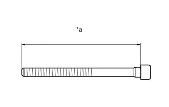
Text in Illustration *a Measurement Length
-
Using a vernier caliper, measure the length of the cylinder head set bolt from the seat to the end.
Standard bolt length 121.0 to 122.0 mm (4.7638 to 4.8031) Maximum bolt length 123.5 mm (4.8622 in.) If the bolt length is greater than the maximum, replace the cylinder head set bolt.
-
-
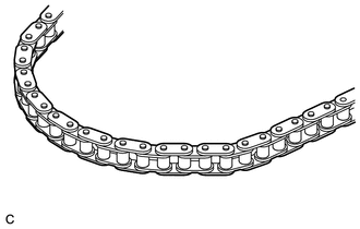
INSPECT CHAIN SUB-ASSEMBLY
-
Visually check the timing chain for wear or cracks.
Tech Tips
If the timing chain is not normal, replace the timing chain and check the sprocket.
-
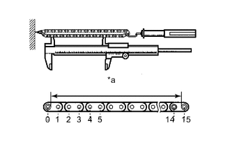
Pull the timing chain with a force of 225 N (23 kgf, 51 lbf) as shown in the illustration.
-
Using a vernier caliper, measure the length of 15 links.
Maximum chain elongation 66.7 mm (2.6260 in.) Tech Tips
Perform the measurement at 3 random places. Use the average of the measurements.
If the average elongation is greater than the maximum, replace the timing chain.
-
-
INSPECT NO. 1 CHAIN TENSIONER ASSEMBLY
-
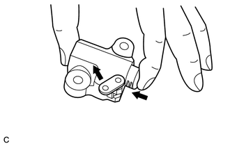
While holding the stopper plate of No. 1 chain tensioner with your fingers, check that the plunger operates smoothly.
-
Release the stopper plate and check that the plunger cannot be pushed with the stopper plate activated.
If No. 1 chain tensioner is not as specified, replace No. 1 chain tensioner.
-