ENGINE UNIT DISASSEMBLY

PROCEDURE
-
REMOVE SPARK PLUG
-
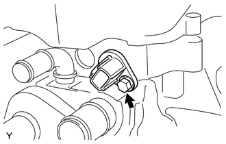
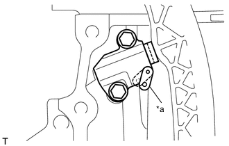
REMOVE CAMSHAFT POSITION SENSOR
-
Remove the bolt and camshaft position sensor.
-
-
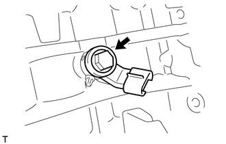
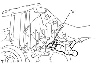
REMOVE ENGINE COOLANT TEMPERATURE SENSOR
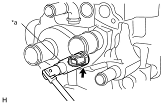
Text in Illustration *a 19 mm Deep Socket Wrench
-
Using a 19 mm deep socket wrench, remove the engine coolant temperature sensor.
-
Remove the gasket from the engine coolant temperature sensor.
-
-
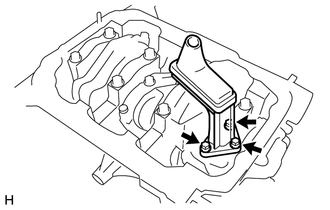
REMOVE CAMSHAFT TIMING OIL CONTROL VALVE ASSEMBLY
-
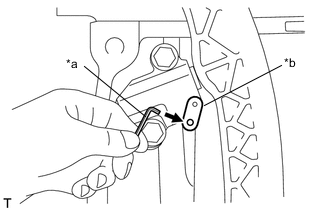
Remove the bolt and camshaft timing oil control valve assembly.
-
-
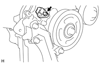
REMOVE CRANKSHAFT POSITION SENSOR
-
Remove the bolt and crankshaft position sensor.
-
-
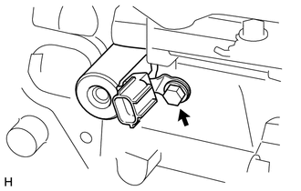
REMOVE KNOCK SENSOR
-
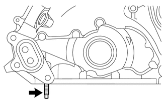
Remove the bolt and knock sensor.
-
-
REMOVE ENGINE OIL PRESSURE SWITCH ASSEMBLY
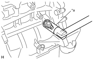
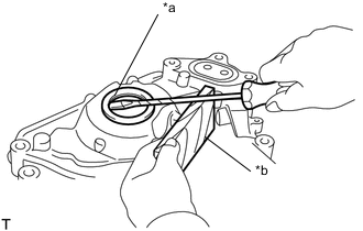
Text in Illustration *a 24 mm Deep Socket Wrench
-
Using a 24 mm deep socket wrench, remove the oil pressure switch assembly.
-
-
REMOVE OIL CONTROL VALVE FILTER
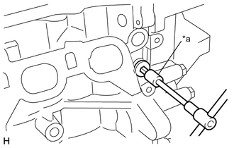
Text in Illustration *a 8 mm Socket Hexagon Wrench
-
Using an 8 mm socket hexagon wrench, remove the head taper screw plug.
-
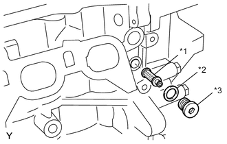
Text in Illustration *1 Oil Control Valve Filter *2 Gasket *3 Head Taper Screw Plug Remove the oil control valve filter and gasket.
-
-
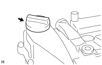
REMOVE OIL FILLER CAP SUB-ASSEMBLY
-
Remove the oil filler cap.
-
Using a screwdriver, remove the oil filler cap gasket from the oil filler cap sub-assembly.
-
-
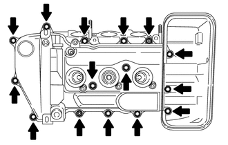
REMOVE CYLINDER HEAD COVER SUB-ASSEMBLY
-
Remove the 13 bolts, 2 nuts and cylinder head cover sub-assembly.
-
Remove the cylinder head cover gasket from the cylinder head cover sub-assembly.
-
-
REMOVE VENTILATION VALVE SUB-ASSEMBLY
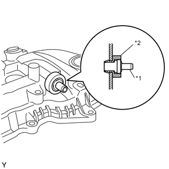
Text in Illustration *1 Ventilation Valve Sub-assembly *2 Grommet
-
Remove the ventilation valve sub-assembly.
-
Remove the grommet.
-
-
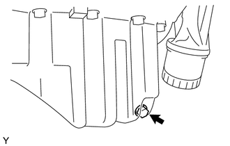
REMOVE OIL PAN DRAIN PLUG
-
Remove the oil pan drain plug.
-
Remove the oil pan drain plug gasket.
-
-
REMOVE OIL PAN SUB-ASSEMBLY (for TMC Made)
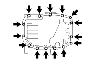
-
Remove the 12 bolts and 3 nuts.
-
Text in Illustration *a Oil Pan Seal Cutter Using an oil pan seal cutter, remove the oil pan sub-assembly.
Note
Be careful not to damage the contact surfaces of the oil pan sub-assembly.
-
-
REMOVE OIL PAN SUB-ASSEMBLY (for TMMF Made)
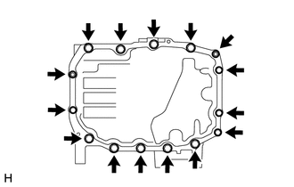
-
Remove the 13 bolts and 2 nuts.
-

Text in Illustration *a Oil Pan Seal Cutter Using an oil pan seal cutter, remove the oil pan sub-assembly.
Note
Be careful not to damage the contact surfaces of the oil pan sub-assembly.
-
-
REMOVE OIL STRAINER SUB-ASSEMBLY
-
Remove the 3 bolts and oil strainer sub-assembly.
-
Remove the oil strainer gasket from the oil strainer sub-assembly.
-
-
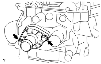
REMOVE WATER INLET
-
Remove the 2 bolts and water inlet.
-
-
REMOVE THERMOSTAT
-
Remove the thermostat with water outlet gasket from the water inlet.
-
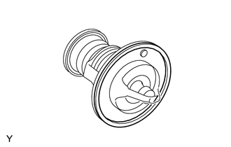
Remove the water outlet gasket from the thermostat.
-
-
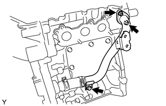
DISCONNECT NO. 1 WATER BY-PASS PIPE
-
Remove the 3 bolts to separate the No. 1 water by-pass pipe from the cylinder head sub-assembly and cylinder block, then remove the water by-pass pipe gasket.
-
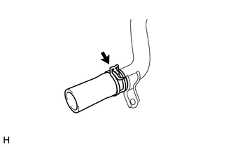
Slide the hose clip and disconnect the water by-pass hose with the No. 1 water by-pass pipe from the timing chain cover sub-assembly.
-
-
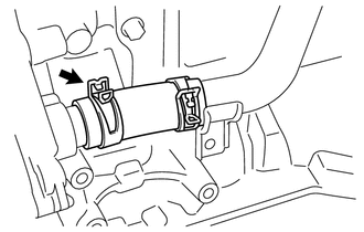
DISCONNECT WATER BY-PASS HOSE
-
Slide the hose clip and disconnect the water by-pass hose from the No. 1 water by-pass pipe.
-
-
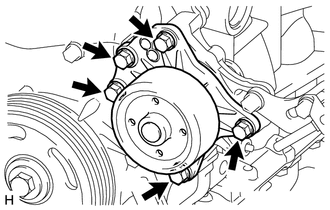
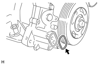
REMOVE ENGINE WATER PUMP ASSEMBLY
-
Remove the 5 bolts and remove the engine water pump assembly.
-
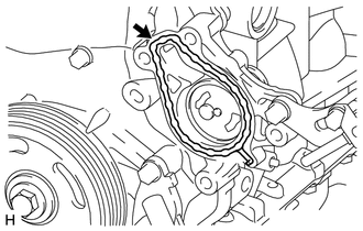
Remove the water pump gasket.
-
-
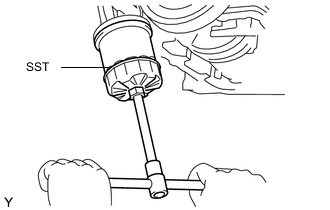
REMOVE OIL FILTER SUB-ASSEMBLY
-
Using SST, remove the oil filter sub-assembly.
- SST
- 09228-06501
-
-
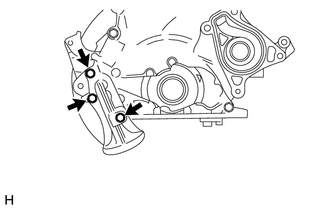
REMOVE OIL FILTER BRACKET
-
Remove the 3 bolts and oil filter bracket.
-
Remove the oil filter bracket gasket from the timing chain cover sub-assembly.
-
-
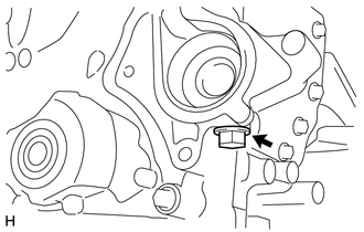
REMOVE TIGHT PLUG
Text in Illustration *a 8 mm Socket Hexagon Wrench
-
Using an 8 mm socket hexagon wrench, remove the tight plug.
-
-
SET NO. 1 CYLINDER TO TDC/EXHAUST
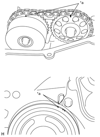
Text in Illustration *a Timing Mark
-
Turn the crankshaft pulley clockwise to align the timing mark on the pulley with the timing mark of the timing chain cover sub-assembly.
-
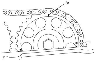
Text in Illustration *a Timing Mark Make sure that the timing mark of the camshaft timing gear is at the top.
-
-
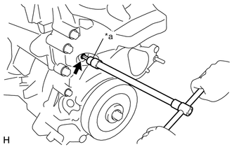
REMOVE CRANKSHAFT PULLEY
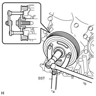
Text in Illustration *a Hold *b Turn
-
Using SST, loosen the crankshaft pulley bolt.
- SST
- 09960-10010 ( 09962-01000, 09963-01000 )
-
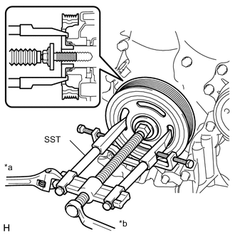
Text in Illustration *a Hold *b Turn Using SST, remove the crankshaft pulley and crankshaft pulley bolt.
- SST
- 09950-40011 ( 09951-04010, 09953-04030, 09958-04011, 09955-04011, 09954-04010, 09952-04010 )
-
-
REMOVE DRAIN PLUG
-
Remove the drain plug and gasket.
-
-
REMOVE TIMING CHAIN COVER SUB-ASSEMBLY
-
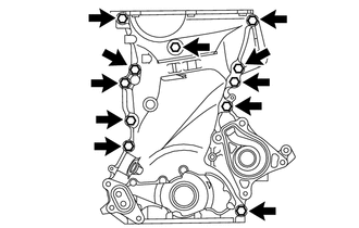
Remove the 11 bolts from the timing chain cover sub-assembly.
-
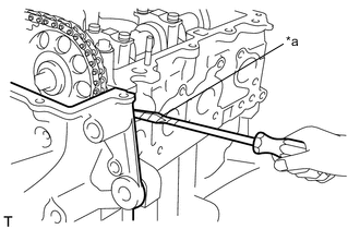
Text in Illustration *a Protective Tape Using a screwdriver with its tip wrapped in protective tape, remove the timing chain cover sub-assembly by prying between the cylinder head sub-assembly and cylinder block.
Note
Do not damage the contact surfaces of the timing chain cover sub-assembly, cylinder head sub-assembly or cylinder block.
-
Remove the oil pump gasket from the cylinder block.
-
-
REMOVE STUD BOLT (for TMC Made)
-
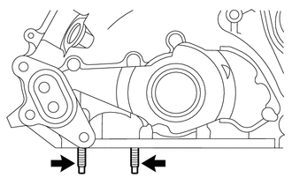
Remove the 2 studs bolt from the timing chain cover sub-assembly.
-
-
REMOVE STUD BOLT (for TMMF Made)
-
Remove the stud bolt from the timing chain cover sub-assembly.
-
-
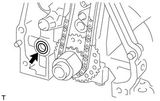
REMOVE TIMING CHAIN COVER OIL SEAL
Text in Illustration *a Protective Tape *b Wooden Block
-
Using a screwdriver with its tip wrapped in protective tape and a wooden block, remove the timing chain cover oil seal from the timing chain cover sub-assembly.
-
-
REMOVE NO. 1 CHAIN TENSIONER ASSEMBLY
-
Turn the stopper plate of the No. 1 chain tensioner assembly clockwise and push in the plunger with the lock released.
Text in Illustration *a Stopper Plate -
Text in Illustration *a Hexagon Wrench *b Stopper Plate Insert a hexagon wrench into the hole in the stopper plate to lock with the plunger pushed in.
-
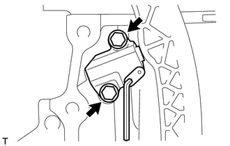
Remove the 2 bolts, No. 1 chain tensioner assembly and chain tensioner gasket from the cylinder block.
-
-
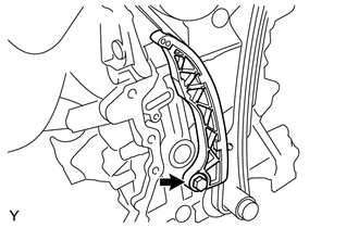
REMOVE TIMING CHAIN TENSION ARM
-
Remove the bolt and timing chain tension arm.
-
-
REMOVE CHAIN SUB-ASSEMBLY
-
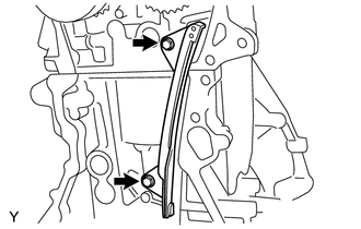
REMOVE TIMING CHAIN GUIDE
-
Remove the 2 bolts and timing chain guide.
-
-
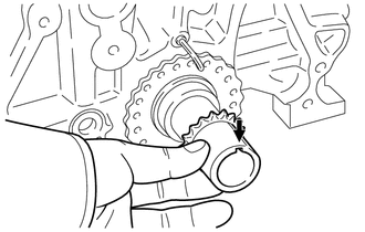
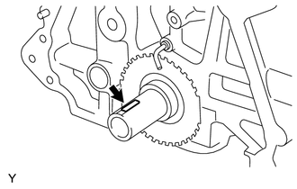
REMOVE CRANKSHAFT TIMING SPROCKET
-
Remove the crankshaft timing sprocket from the crankshaft.
-
-
REMOVE CRANKSHAFT STRAIGHT PIN
-
Remove the crankshaft straight pin from the crankshaft.
-
-
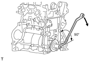
REMOVE CAMSHAFT TIMING SPROCKET ASSEMBLY
-
Rotate the crankshaft 90° clockwise.
Note
Do not allow the lifted valve and piston to come into the contact with each other when removing the camshaft.
-
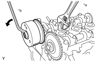
Text in Illustration *a Hold *b Turn Remove the bolt from the camshaft timing sprocket assembly while holding the hexagonal portion of the camshaft.
-
Remove the camshaft timing sprocket assembly from the camshaft.
-
-
REMOVE CAMSHAFT TIMING GEAR
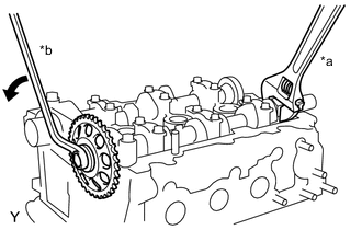
Text in Illustration *a Hold *b Turn
-
Remove the bolt from the gear while holding the hexagonal portion of the No. 2 camshaft.
-
Remove the camshaft timing gear from the No. 2 camshaft.
-
-
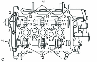
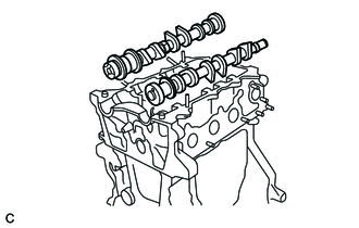
REMOVE CAMSHAFTS
-
Remove the 15 bolts in the order shown in the illustration.
Text in Illustration *1 No. 1 Camshaft Bearing Cap *2 No. 2 Camshaft Bearing Cap -
Remove the No. 1 camshaft bearing cap and No. 2 camshaft bearing caps.
-
Remove the camshaft and No. 2 camshaft.
-
-
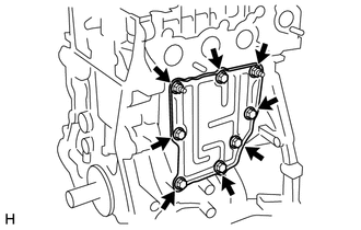
REMOVE VENTILATION BAFFLE PLATE
-
Remove the 6 bolts, 2 nuts and ventilation baffle plate from the cylinder block.
-
-
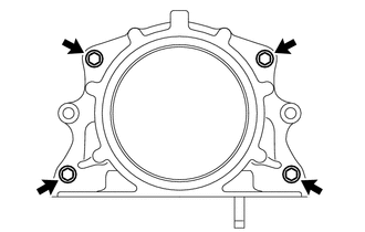
REMOVE ENGINE REAR OIL SEAL RETAINER
-
Remove the 4 bolts and engine rear oil seal retainer from the cylinder block.
-
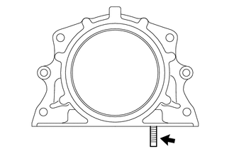
Remove the stud bolt from the engine rear oil seal retainer.
-
-
REMOVE ENGINE REAR OIL SEAL
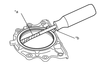
Text in Illustration *a Protective Tape *b Wooden Block
-
Using a screwdriver with its tip wrapped in protective tape and a wooden block, remove the engine rear oil seal from the engine rear oil seal retainer.
-
-
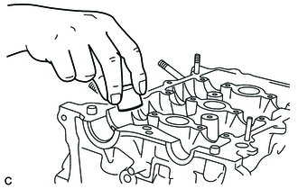
REMOVE VALVE LIFTER
-
Remove the 12 valve lifters.
Note
-
Record the inscribed mark on the valve lifters for each valve after removing them.
-
Arrange the valve lifters for each cylinder in order.
-
-
-
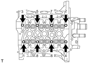
REMOVE CYLINDER HEAD SUB-ASSEMBLY
-
Using several steps, uniformly loosen and remove the 8 cylinder head set bolts and 8 plate washers with an 8 mm bi-hexagon wrench in the sequence shown in the illustration.
Note
-
Head warpage or cracking could result from removing the cylinder head set bolts in the wrong order.
-
Do not drop the washers into the cylinder head sub-assembly.
-
-
Remove the cylinder head sub-assembly from the cylinder block.
-
-
REMOVE CYLINDER HEAD GASKET
-
REMOVE CYLINDER BLOCK WATER JACKET SPACER
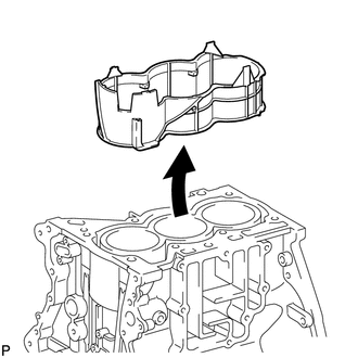
-
Remove the cylinder block water jacket spacer from the cylinder block.
-