ENGINE UNIT REMOVAL

PROCEDURE
-
REMOVE NO. 1 WATER BY-PASS HOSE
-
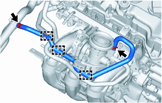
Disengage the 3 clamps to separate the No. 1 water by-pass hose from the intake manifold and hose clamp.
-
Slide the 2 hose clips and remove the No. 1 water by-pass hose from the throttle body with motor assembly and inlet heater water hose A.
-
-
REMOVE NO. 2 WATER BY-PASS HOSE
-
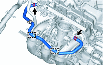
Disengage the 2 clamps to separate the No. 2 water by-pass hose from the intake manifold.
-
Slide the 2 hose clips and remove the No. 2 water by-pass hose from the throttle body with motor assembly and EGR valve assembly.
-
-
REMOVE INLET HEATER WATER HOSE A
-
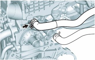
Slide the hose clip and remove the inlet heater water hose A from the cylinder head sub-assembly.
-
-
REMOVE NO. 2 WATER BY-PASS HOSE
-
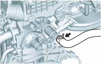
Slide the hose clip and remove the No. 2 water by-pass hose from the cylinder head sub-assembly.
-
-
REMOVE AIR CLEANER CAP SUPPORT
-
REMOVE THROTTLE BODY WITH MOTOR ASSEMBLY
-
REMOVE THROTTLE BODY GASKET
-
REMOVE EFI FUEL PIPE CLAMP
-
REMOVE FUEL TUBE SUB-ASSEMBLY
-
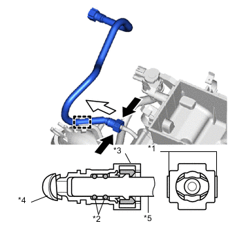
Text in Illustration *1 Retainer *2 O-ring *3 Fuel Tube Connector *4 Nylon Tube *5 Fuel Pipe 
Pinch 
Pull Disengage the clamp to separate the fuel tube sub-assembly from the fuel hose clamp.
-
Remove the fuel tube sub-assembly from the fuel delivery pipe.
-
Pinch the retainer of the fuel tube connector, and then pull the fuel tube connector off of the fuel pipe.
Note
Be sure to disconnect the fuel tube connector by hand.
-
If the fuel tube connector and fuel pipe are stuck, push and pull the fuel tube connector to release it. Pull the fuel tube connector off of the fuel pipe carefully.
Note
-
Be sure to disconnect the fuel tube connector by hand.
-
Do not allow any scratches or foreign matter to get on the parts when disconnecting them as the fuel tube connector has O-rings that seal the fuel pipe.
-
Do not forcibly bend, twist or turn the nylon tube.
-
-
Check if there is any foreign matter on the sealing surfaces of the disconnected fuel lines. Clean them if necessary.
-
Cover the disconnected fuel pipe and fuel tube connector with plastic bags to prevent damage and contamination.
Note
Do not damage the fuel tube connector and fuel pipe, and do not allow foreign matter to enter the fuel pipe.
-
-
-
REMOVE WIRE HARNESS CLAMP BRACKET
-
Remove the bolt and wire harness clamp bracket from the cylinder head cover sub-assembly.
-
-
REMOVE INTAKE MANIFOLD
-
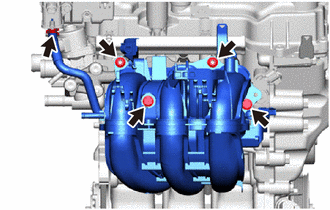
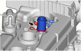
Slide the hose clip and disconnect the No. 2 fuel vapor feed hose from the duty vacuum switching valve.
-
Remove the 2 bolts, 2 nuts and intake manifold from the cylinder head sub-assembly.
-
-
REMOVE NO. 1 INTAKE MANIFOLD TO HEAD GASKET
-
REMOVE NO. 1 INTAKE MANIFOLD INSULATOR
-
REMOVE NO. 2 INTAKE MANIFOLD TO HEAD GASKET
-
REMOVE EGR VALVE ASSEMBLY
-
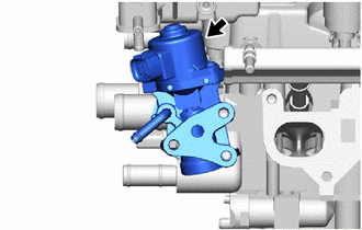
Remove the EGR valve assembly from the cylinder head sub-assembly.
-
-
REMOVE EGR VALVE GASKET
-
REMOVE MANIFOLD STAY
-
REMOVE EXHAUST MANIFOLD
-
REMOVE EXHAUST MANIFOLD TO HEAD GASKET
-
REMOVE INLET EGR GASKET
-
REMOVE NO. 1 IGNITION COIL
-
REMOVE FUEL DELIVERY PIPE
-
Make sure that there are no deposits such as sand or grit near the fuel injector assembly, and if there are any deposits, clean them away.
Note
Do not allow foreign matter to enter any other components.
-
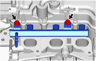
Using a 12 mm union nut wrench, loosen bolt A.
Tech Tips
Bolt A interferes with the cylinder head cover sub-assembly and cannot be removed by itself, so remove it together with the fuel delivery pipe.
-
Remove bolt B.
-
Remove the fuel delivery pipe with the fuel injector assembly and bolt A from the cylinder head sub-assembly.
Note
-
Do not allow any foreign matter to enter the cylinder head sub-assembly.
-
Do not drop the fuel injector assemblies when removing the fuel delivery pipe.
-
-
-
REMOVE INJECTOR VIBRATION INSULATOR
-
REMOVE FUEL PIPE INSULATOR
-
REMOVE FUEL INJECTOR ASSEMBLY
-
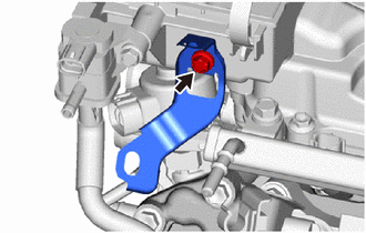
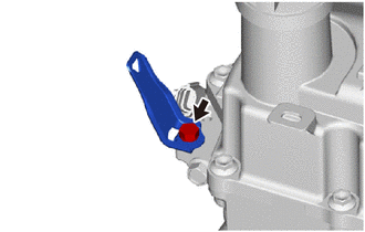
REMOVE DUTY VACUUM SWITCHING VALVE
-
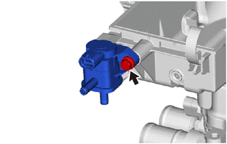
Remove the bolt and duty vacuum switching valve from the cylinder head cover sub-assembly.
-
-
REMOVE V-RIBBED BELT TENSIONER ASSEMBLY
-
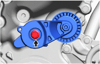
Remove the bolt and V-ribbed belt tensioner assembly from the timing chain cover sub-assembly.
-
-
REMOVE VENTILATION HOSE
-
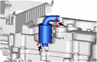
Slide the 2 hose clips and remove the ventilation hose from the PCV valve (ventilation valve sub-assembly) and cylinder head cover sub-assembly.
-
-
REMOVE NO. 2 VENTILATION HOSE
-
Slide the hose clip and remove the No. 2 ventilation hose from the cylinder head cover sub-assembly.
-
-
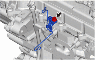
REMOVE WIRE HARNESS CLAMP BRACKET
-
Remove the bolt and wire harness clamp bracket from the timing chain cover sub-assembly.
-
Remove the bolt and wire harness clamp bracket from the cylinder head cover sub-assembly.
-