ENGINE ASSEMBLY INSTALLATION

CAUTION / NOTICE / HINT
Note
As the engine assembly with transaxle is extremely heavy, the engine lifter may suddenly drop if the instructions listed in the repair manual are not followed. Therefore, always follow the instructions listed in the repair manual when performing this procedure.
PROCEDURE
-
INSTALL ENGINE MOUNTING INSULATOR LH
Tech Tips
Only perform this procedure when replacement of the engine mounting insulator LH is necessary.
-
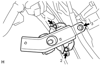
Temporarily install the engine mounting insulator LH with the 3 bolts.
-
Fully tighten the 3 bolts, in the order shown in the illustration.
- Torque:
- 52 N*m { 530 kgf*cm, 38 ft.*lbf }
-
-
INSTALL ENGINE MOUNTING INSULATOR SUB-ASSEMBLY RH
Tech Tips
Only perform this procedure when replacement of the engine mounting insulator RH is necessary.
-
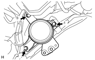
Temporarily install the engine mounting insulator RH with the 3 bolts.
-
Fully tighten the 3 bolts, in the order shown in the illustration.
- Torque:
- 52 N*m { 530 kgf*cm, 38 ft.*lbf }
-
-
INSTALL FLYWHEEL SUB-ASSEMBLY
-
INSTALL CLUTCH DISC ASSEMBLY
-
INSTALL CLUTCH COVER ASSEMBLY
-
INSPECT AND ADJUST CLUTCH COVER ASSEMBLY
-
INSTALL ENGINE ASSEMBLY
-
Align the input shaft with the clutch disc and install the engine to the manual transaxle.
-
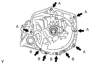
Install the 9 bolts.
- Torque:
- Bolt A
- 64 N*m { 653 kgf*cm, 47 ft.*lbf }
- Bolt B
- 39 N*m { 398 kgf*cm, 29 ft.*lbf }
Note
Insert knock pins into the knock pin holes securely so that the end face of the transaxle fits close against the engine before tightening the bolts.
-
-
INSTALL STARTER ASSEMBLY
-
INSTALL FLYWHEEL HOUSING SIDE COVER
-
INSTALL ENGINE WIRE
-
Install the engine wire to the engine.
-
-
INSTALL ENGINE ASSEMBLY WITH TRANSAXLE
-
Place wooden blocks or plate lift attachments on an engine lifter, and then set the engine assembly with transaxle.
Note
-
Place the wooden blocks or plate lift attachments so that the engine assembly with transaxle is level.
-
As the engine assembly with transaxle is very heavy, be sure to support it securely.
-
-
Operate the engine lifter and lift the engine assembly with transaxle and the front suspension crossmember to the position where the engine mounting insulators RH and LH can be installed.
-
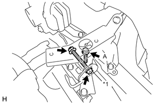
Text in Illustration *1 Through Bolt Temporarily install the engine mounting insulator LH with the bolt, through bolt and nut.
-
Fully tighten the bolt A.
- Torque:
- Bolt A
- 64 N*m { 653 kgf*cm, 47 ft.*lbf }
-
Fully tighten the through bolt and nut.
- Torque:
- Through Bolt
- 52 N*m { 530 kgf*cm, 38 ft.*lbf }
-
Install the engine mounting insulator RH with the bolt and 2 nuts.
- Torque:
- 52 N*m { 530 kgf*cm, 38 ft.*lbf }
-
By inserting SST into the datum holes in the front suspension crossmember RH and LH alternately, tighten bolts A, B and C on both sides to the specified torque, in several steps.
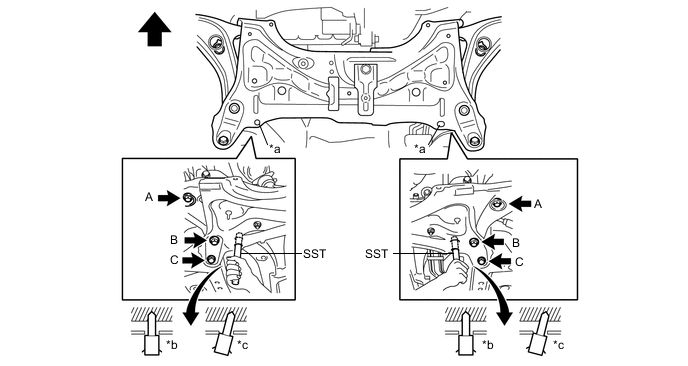
Text in Illustration *a Datum Hole *b OK *c NG - - 
Front of the Vehicle - - - SST
- 09670-00011
- Torque:
- Bolt A
- 87 N*m { 887 kgf*cm, 64 ft.*lbf }
- Bolt B
- 151 N*m { 1540 kgf*cm, 111 ft.*lbf }
- Bolt C
- 98 N*m { 999 kgf*cm, 72 ft.*lbf }
Note
-
Insert SST into the datum hole vertically.
-
If impossible to insert SST vertically, loosen all bolts and then insert SST again.
-
Install the wire harness clamp bracket with the bolt.
T = 29 N*m{ kgf*cm 21 ft.*lbf }
-
-
INSTALL NO. 1 STEERING COLUMN HOLE COVER SUB-ASSEMBLY
-
INSTALL STEERING SLIDING YOKE SUB-ASSEMBLY
-
INSTALL COLUMN HOLE COVER SILENCER SHEET
-
INSTALL FRONT DRIVE SHAFT ASSEMBLY
-
CONNECT TRANSMISSION CONTROL CABLE ASSEMBLY
-
INSTALL CLUTCH RELEASE CYLINDER ASSEMBLY
-
INSTALL RELEASE CYLINDER HEAT INSULATOR
-
CONNECT ENGINE WIRE
-
Engage the wire harness clamp.
-
Install the bolt and connect the ground wire from the transaxle.
- Torque:
- 26 N*m { 260 kgf*cm, 19 ft.*lbf }
-
Engage the 2 claws and connect the wire harness to the junction block.
-
Connect the connector to the engine junction block.
-
Disengage the wire harness clamp.
-
Remove the engine junction block cover.
-
Connect the connector to the ECM, and slide the lever to engage the lock.
Note
-
Make sure that the levers are securely locked.
-
-
Connect the current sensor connector to the negative (-) battery terminal.
-
Connect the 2 connectors to the positive (+) battery terminal.
-
-
INSTALL FRONT EXHAUST PIPE ASSEMBLY
-
CONNECT NO. 2 HEATED OXYGEN SENSOR WIRE HARNESS
-
Engage the 3 clamps and connect the No. 2 heated oxygen sensor wire to the fan shroud.
-
Connect the No. 2 heated oxygen sensor connector.
-
-
INSTALL TAIL EXHAUST PIPE ASSEMBLY
-
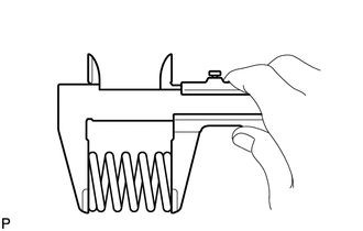
Using a vernier caliper, measure the free length of the compression spring.
Minimum Length 38.5 mm (1.516 in.) Tech Tips
If the length is not as specified, replace the compression spring.
-
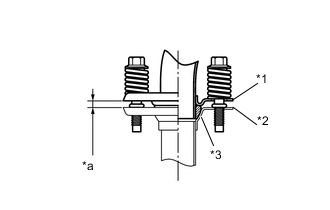
Text in Illustration *1 Exhaust Pipe Gasket *2 Wooden Block *3 Plastic Hammer *4 Front Exhaust Pipe Assembly Using a plastic hammer and a wooden block, tap in a new exhaust pipe gasket until its surface is flush with the front exhaust pipe.
Note
-
Install the gasket in the correct direction.
-
Do not reuse the gasket.
-
Do not damage the gasket by dropping it, etc.
-
Do not damage the outer surface of the gasket.
-
Do not push in the gasket with the exhaust pipe when connecting it.
-
-
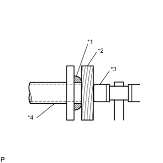
Text in Illustration *1 Front Exhaust Pipe Assembly *2 Tail Exhaust Pipe Assembly *3 Exhaust Pipe Gasket *a Space between flanges: 6.5 mm (0.256 in.) Install the front exhaust pipe to the exhaust manifold converter with the 2 compression springs and 2 bolts.
- Torque:
- 43 N*m { 438 kgf*cm, 32 ft.*lbf }
Note
After the installation, check that the gaps between the flanges of the front exhaust pipe and tail exhaust pipe are consistent front-to-rear and left-to-right.
-
-
INSTALL FRONT FLOOR CENTER BRACE
-
CONNECT NO. 2 RADIATOR HOSE
-
Connect the No. 2 radiator hose to the water inlet.
-
-
CONNECT NO. 1 RADIATOR HOSE
-
Connect the No. 1 radiator hose to the cylinder head.
-
-
CONNECT BOOSTER VACUUM TUBE
-
Connect the booster vacuum tube connector to the intake manifold.
-
Engage the booster vacuum tube to the hose clamp.
-
-
CONNECT INLET HEATER WATER HOSE A
-
Connect the inlet heater water hose to the air conditioning unit.
-
-
CONNECT OUTLET HEATER WATER HOSE A
-
Connect the outlet heater water hose to the air conditioning unit.
-
-
CONNECT NO. 1 FUEL VAPOR FEED HOSE
-
Connect the No. 1 fuel vapor feed hose to the duty vacuum switching valve.
-
Engage the No. 1 fuel vapor feed hose to the hose clamp.
-
-
CONNECT FUEL TUBE SUB-ASSEMBLY
-
Connect the fuel tube Click here.
-
-
INSTALL EFI FUEL PIPE CLAMP
-
Install the fuel pipe clamp.
-
-
INSTALL COMPRESSOR ASSEMBLY WITH PULLEY
-
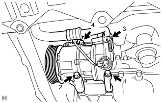
Temporarily install the compressor with the 4 bolts.
-
Fully tighten the 4 bolts, in the order shown in the illustration.
- Torque:
- 25 N*m { 250 kgf*cm, 18 ft.*lbf }
-
Connect the compressor connector.
-
-
INSTALL GENERATOR ASSEMBLY
-
INSTALL FAN AND GENERATOR V BELT
-
INSTALL BATTERY CARRIER (for LHD)
-
Install the battery carrier with the 4 bolts.
- Torque:
- 17 N*m { 175 kgf*cm, 13 ft.*lbf }
-
Engage the 4 clamps and connect the wire harness onto the battery carrier.
-
-
INSTALL BATTERY CARRIER (for RHD)
-
Install the battery carrier with the 4 bolts.
- Torque:
- 17 N*m { 175 kgf*cm, 13 ft.*lbf }
-
Engage the 5 clamps and connect the wire harness onto the battery carrier.
-
-
INSTALL BATTERY TRAY
-
Install the battery tray.
-
-
INSTALL BATTERY
-
Install the battery onto the battery tray.
-
Install the battery clamp with the 2 nuts.
- Torque:
- 3.5 N*m { 36 kgf*cm, 31 in.*lbf }
-
Connect the cable to the positive (+) battery terminal.
- Torque:
- 5.4 N*m { 55 kgf*cm, 48 in.*lbf }
-
-
INSTALL FRONT WHEEL
- Torque:
- 103 N*m { 1050 kgf*cm, 76 ft.*lbf }
-
INSPECT FAN AND GENERATOR V BELT
-
ADD ENGINE OIL
-
ADD ENGINE COOLANT
-
ADD MANUAL TRANSAXLE OIL
-
INSPECT ENGINE OIL LEVEL
-
INSPECT FOR ENGINE OIL LEAK
-
INSPECT FOR COOLANT LEAK
-
INSPECT FOR EXHAUST GAS LEAK
-
INSPECT FOR FUEL LEAK
-
INSTALL ENGINE UNDER COVER RH
- Torque:
- 5.0 N*m { 51 kgf*cm, 44 in.*lbf }
-
INSTALL ENGINE UNDER COVER LH
- Torque:
- 5.0 N*m { 51 kgf*cm, 44 in.*lbf }
-
INSPECT AND ADJUST FRONT WHEEL ALIGNMENT
-
CHECK SPEED SENSOR SIGNAL (w/o VSC)
-
CHECK SPEED SENSOR SIGNAL (for TMC Made with VSC)
-
CHECK SPEED SENSOR SIGNAL (for TMMF Made with VSC)