ENGINE ASSEMBLY REMOVAL

CAUTION / NOTICE / HINT
Note
As the engine assembly with transaxle is extremely heavy, the engine lifter may suddenly drop if the instructions listed in the repair manual are not followed. Therefore, always follow the instructions listed in the repair manual when performing this procedure.
PROCEDURE
-
PRECAUTION
Note
After turning the ignition switch off, waiting time may be required before disconnecting the cable from the battery terminal. Therefore, make sure to read the disconnecting the cable from the battery terminal notice before proceeding with work Click here.
-
DISCHARGE FUEL SYSTEM PRESSURE
-
DISCONNECT CABLE FROM NEGATIVE BATTERY TERMINAL
Note
When disconnecting the cable, some systems need to be initialized after the cable is reconnected Click here.
-
REMOVE FRONT WHEEL
-
REMOVE ENGINE UNDER COVER LH
-
Remove the 3 bolts, 3 screws and engine under cover LH from the vehicle.
-
-
REMOVE ENGINE UNDER COVER RH
-
Remove the 2 bolts, screw and engine under cover RH from the vehicle.
-
-
DRAIN ENGINE COOLANT
-
DRAIN MANUAL TRANSAXLE OIL
-
REMOVE WINDSHIELD WIPER MOTOR AND LINK
-
REMOVE FRONT NO. 1 VENTILATOR SEAL (for LHD)
-
REMOVE FRONT NO. 1 VENTILATOR SEAL (for RHD)
-
REMOVE FRONT AIR SHUTTER SEAL RH (for LHD)
-
REMOVE FRONT AIR SHUTTER SEAL RH (for RHD)
-
REMOVE INNER COWL TOP TO COWL BRACE (for LHD)
-
REMOVE INNER COWL TOP TO COWL BRACE (for RHD)
-
REMOVE OUTER COWL TOP PANEL (for LHD)
-
REMOVE OUTER COWL TOP PANEL (for RHD)
-
REMOVE BATTERY
-
Open the positive (+) battery terminal cover.
-
Loosen the nut and disconnect the cable from the positive (+) battery terminal.
-
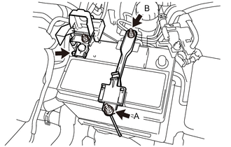
Loosen the nut A.
-
Remove the nut B and battery clamp sub-assembly from the battery carrier.
-
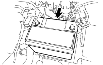
Remove the battery from the battery tray.
-
-
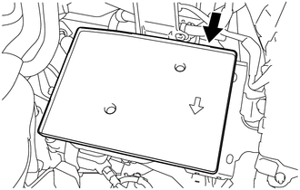
REMOVE BATTERY TRAY
-
Remove the battery tray from the battery carrier.
-
-
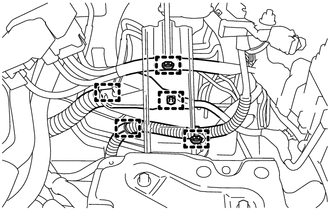
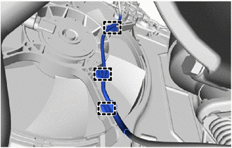
SEPARATE BATTERY CARRIER
-
Disengage the 5 clamps to disconnect the engine wire from the battery carrier.
-
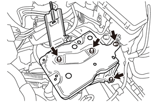
Remove the 4 bolts and battery carrier from the vehicle.
-
-
REMOVE INLET NO. 1 AIR CLEANER
-
REMOVE AIR CLEANER CAP SUB-ASSEMBLY
-
REMOVE AIR CLEANER FILTER ELEMENT SUB-ASSEMBLY
-
REMOVE FAN AND GENERATOR V BELT
-
REMOVE GENERATOR ASSEMBLY (for DENSO Made)
-
REMOVE GENERATOR ASSEMBLY (for VALEO Made)
-
SEPARATE COMPRESSOR ASSEMBLY WITH PULLEY (w/ Air Conditioning System)
-
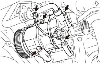
Disconnect the compressor assembly with pulley connector.
-
Remove the 4 bolts to separate the compressor assembly with pulley from the cylinder block sub-assembly and oil pan sub-assembly.
Tech Tips
It is not necessary to completely remove the compressor assembly with pulley. With the No. 1 cooler refrigerant discharge hose suction hose sub-assembly connected to the compressor, hang the compressor on the vehicle body with a rope.
-
-
REMOVE EFI FUEL PIPE CLAMP
Note
Before disconnecting the fuel tube connector, make sure there are no deposits, clean them away.
-
Remove the EFI fuel pipe clamp from the fuel tube sub-assembly and fuel tube.
-
-
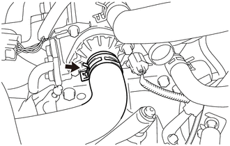
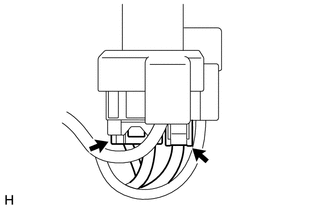
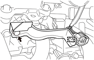
DISCONNECT FUEL TUBE SUB-ASSEMBLY
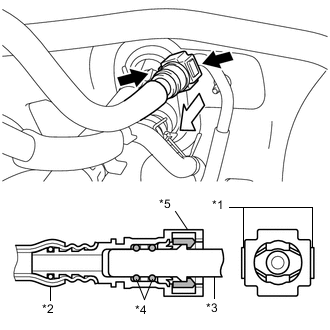
Text in Illustration *1 Retainer *2 Nylon Tube *3 Pipe *4 O-ring *5 Fuel Tube Connector 
Pinch 
Pull
-
Disconnect the fuel tube sub-assembly from the fuel tube.
-
Pinch the retainer of the fuel tube connector, and then pull the fuel tube connector off of the fuel pipe.
Note
Be sure to disconnect the fuel tube connector by hand.
-
If the fuel tube connector and fuel pipe are stuck, push and pull the fuel tube connector to release it.
-
Pull the fuel tube connector off of the fuel pipe carefully.
Note
-
Be sure to disconnect the fuel tube connector by hand.
-
Do not allow any scratches or foreign matter to get on the parts when disconnecting them as the fuel tube connector has O-rings that seal the fuel pipe.
-
Do not forcibly bend, twist or turn the nylon tube.
-
-
Check if there is any foreign matter on the sealing surfaces of the disconnected fuel lines. Clean them if necessary.
-
Cover the disconnected fuel tube connector and fuel pipe with plastic bags to prevent damage and contamination.
-
-
-
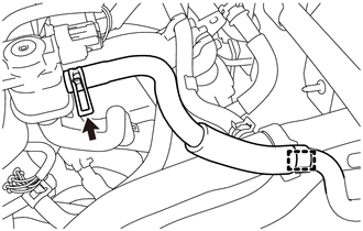
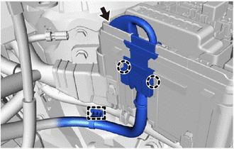
SEPARATE NO. 1 FUEL VAPOR FEED HOSE
-
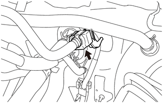
Disengage the clamp to disconnect the No. 1 fuel vapor feed hose from the hose clamp.
-
Slide the hose clip and disconnect the No. 1 fuel vapor feed hose from the duty vacuum switching valve.
-
-
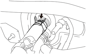
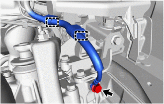
SEPARATE OUTLET HEATER WATER HOSE A
-
Slide the hose clip and disconnect the outlet heater water hose A from the heater unit.
-
-
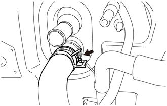
DISCONNECT INLET HEATER WATER HOSE A
-
Slide the hose clip and disconnect the inlet heater water hose A from the heater unit.
-
-
DISCONNECT VACUUM HOSE ASSEMBLY
-
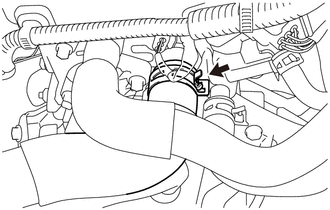
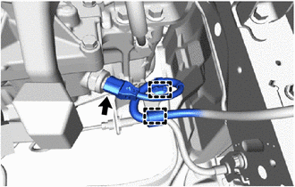
SEPARATE NO. 1 RADIATOR HOSE
-
Slide the hose clip and disconnect the No. 1 radiator hose from the cylinder head sub-assembly.
-
-
SEPARATE NO. 2 RADIATOR HOSE
-
Slide the hose clip and disconnect the No. 2 radiator hose from the water inlet.
-
-
REMOVE FRONT FLOOR CENTER BRACE
-
REMOVE FRONT EXHAUST PIPE ASSEMBLY
-
Disconnect the No. 2 heated oxygen sensor connector.
-
Disengage the 3 clamps to disconnect the No. 2 heated oxygen sensor connector wire from the fan shroud.
-
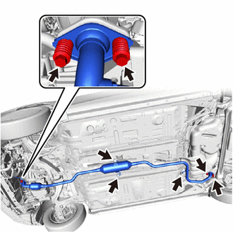
Remove the 2 bolts, 2 compression spring to separate the front exhaust pipe assembly from the tail exhaust pipe assembly.
-
Remove the 2 bolts, 2 compression spring to separate the front exhaust pipe assembly from the exhaust manifold.
-
Disconnect the 3 exhaust pipe supports to remove the front exhaust pipe assembly from the vehicle.
-
Remove the exhaust pipe gasket from the exhaust manifold.
-
Remove the No. 2 exhaust pipe gasket from the front exhaust pipe assembly.
-
-
DISCONNECT ENGINE WIRE
-
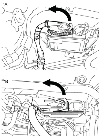
Text in Illustration *A for LHD *B for RHD Raise the lever while pushing the lock on the lever to disconnect the ECM connector.
-
for LHD:
-
Disengage the clamp to disconnect the engine wire from the wire harness clamp bracket.
-
-
Remove the engine room relay block cover.
-
Disengage the clamp to disconnect the engine wire from the vehicle.
-
Disconnect the connector from the engine room relay block.
-
Disengage the 2 claws to disconnect the engine wire from the engine room block.
-
Disconnect the 2 connectors from the positive (+) battery terminal.
-
Remove the bolt to disconnect the engine wire from the transaxle.
-
Disengage the 2 clamps to disconnect the engine wire from the transaxle.
-
w/ Stop and Start System:
-
Disconnect the neutral position switch connector.
-
Disengage the 2 clamps to disconnect the engine wire from the wire harness clamp bracket.
-
Remove the bolt and wire harness clamp bracket from the clutch flexible hose bracket.
-
-
-
REMOVE RELEASE CYLINDER HEAT INSULATOR
-
SEPARATE CLUTCH RELEASE CYLINDER ASSEMBLY
-
DISCONNECT TRANSMISSION CONTROL CABLE ASSEMBLY
-
REMOVE DRIVE SHAFT HEAT INSULATOR SUB-ASSEMBLY
-
REMOVE FRONT DRIVE SHAFT ASSEMBLY
-
REMOVE COLUMN HOLE COVER SILENCER SHEET
-
SEPARATE STEERING SLIDING YOKE SUB-ASSEMBLY
-
SEPARATE NO. 1 STEERING COLUMN HOLE COVER SUB-ASSEMBLY
-
REMOVE ENGINE ASSEMBLY WITH TRANSAXLE
-
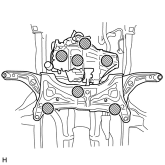
Place the height adjustment or plate lift attachments in the positions shown in the illustration and set an engine lifter underneath the engine assembly with transaxle.
Text in Illustration 
Attachment Placement Position Note
-
Place the height adjustment or plate lift attachments so that the engine assembly with transaxle is level.
-
Do not perform any procedure while the engine assembly is suspended because doing so may cause the engine assembly to drop, resulting in injury. However, the engine assembly needs to be suspended when it is installed to or removed from an engine stand.
-
As the engine assembly with transaxle is very heavy, be sure to support it securely.
-
-
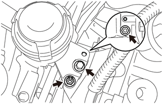
Remove the bolt and 2 nuts to separate the engine mounting insulator sub-assembly RH from the timing chain cover sub-assembly.
-
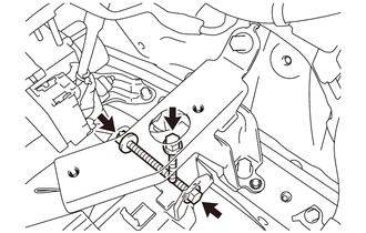
Remove the bolt, through bolt, nut to separate the engine mounting insulator LH from the engine mounting bracket LH.
Tech Tips
Loosen by holding the nut and turning the through bolt.
-
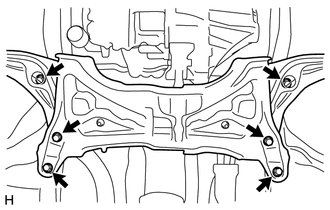
Remove the 6 bolts, the engine assembly with transaxle and front suspension crossmember from the vehicle.
Note
When removing the engine assembly with transaxle, be careful not to damage any wire harnesses or the steering shaft.
-
-
REMOVE WIRE HARNESS CLAMP BRACKET
-
Disengage the clamp to disconnect the engine wire from the wire harness clamp bracket.
-
Remove the bolt and wire harness clamp bracket from the cylinder head sub-assembly.
-
-
INSTALL ENGINE HANGER
-
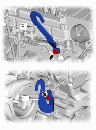
Text in Illustration *1 No. 1 Engine Hanger *2 No. 2 Engine Hanger Install the No. 1 engine hanger and No. 2 engine hanger to the cylinder head sub-assembly with the 2 bolts.
- Torque:
- 20 N*m { 204 kgf*cm, 15 ft.*lbf }
Tech Tips
Part Name Part No. No. 1 Engine Hanger 12281-40032 No. 2 Engine Hanger 12282-40010 Bolt 91671-80820
-
-
FIX ENGINE ASSEMBLY WITH TRANSAXLE
-
Using an engine sling device and a chain block, hold the engine assembly with transaxle.
-
To enable removal of the engine assembly with transaxle, adjust the positions of the height adjustment or plate lift attachments and set them in place.
Note
-
Set the height adjustment or plate lift attachments so that the engine assembly with transaxle is level.
-
Do not perform any procedure while the engine assembly is suspended because doing so may cause the engine assembly to drop, resulting in injury. However, the engine assembly needs to be suspended when it is installed to or removed from an engine stand.
-
-
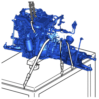
Use a belt with a tighten mechanism or a rope to secure the engine assembly with transaxle to the engine lifter.
Note
-
Do not tighten the belt with a tightening mechanism or the rope any more than is necessary.
-
Set the engine assembly with transaxle so that it is horizontal.
-
-
-
REMOVE ENGINE WIRE
-
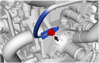
Remove the bolt to disconnect the engine wire from the cylinder head sub-assembly.
-
Disconnect all the wire harnesses and connectors. Make sure that no wire harnesses are connected to the engine assembly.
-
-
REMOVE FLYWHEEL HOUSING SIDE COVER (w/ Stop And Start System)
-
REMOVE FLYWHEEL HOUSING SIDE COVER (for Cold Area Specification Vehicles)
-
REMOVE FLYWHEEL HOUSING SIDE COVER (except Cold Area Specification Vehicles)
-
REMOVE STARTER ASSEMBLY (w/ Stop And Start System)
-
REMOVE STARTER ASSEMBLY (for Cold Area Specification Vehicles)
-
REMOVE STARTER ASSEMBLY (except Cold Area Specification Vehicles)
-
REMOVE MANUAL TRANSAXLE ASSEMBLY
-
REMOVE CLUTCH COVER ASSEMBLY
-
REMOVE CLUTCH DISC ASSEMBLY
-
REMOVE FLYWHEEL SUB-ASSEMBLY
-
INSTALL ENGINE STAND
-
Install the engine assembly to an engine stand.
Note
-
Adjust the angle of the sling device carefully to prevent the engine assembly or engine hangers from deforming or becoming damaged.
-
Servicing an engine assembly while it is hanging is dangerous. This can be done only when installing/removing the engine assembly to/from an engine stand.
-
-
-
REMOVE ENGINE MOUNTING INSULATOR SUB-ASSEMBLY RH
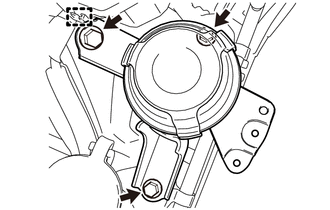
Tech Tips
Only perform this procedure when replacement of the engine mounting insulator sub-assembly RH is necessary.
-
Remove the 3 bolts.
-
Disengage the hook to remove the engine mounting insulator sub-assembly RH from the vehicle.
-
-
REMOVE ENGINE MOUNTING INSULATOR LH
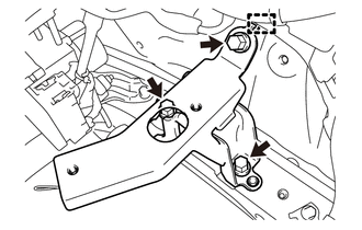
Tech Tips
Only perform this procedure when replacement of the engine mounting insulator LH is necessary.
-
Remove the 3 bolts.
-
Disengage the hook to remove the engine mounting insulator LH from the vehicle.
-
-
REMOVE ENGINE HANGER
-
Remove the 2 bolts, No. 1 engine hanger and No. 2 engine hanger from the cylinder head sub-assembly.
-