ENGINE ASSEMBLY REMOVAL

CAUTION / NOTICE / HINT
CAUTION:
As the engine assembly with transaxle is extremely heavy, the engine lifter may suddenly drop if the instructions listed in the repair manual are not followed. Therefore, always follow the instructions listed in the repair manual when performing this procedure.
PROCEDURE
-
PRECAUTION
Note
After turning the ignition switch off, waiting time may be required before disconnecting the cable from the battery terminal. Therefore, make sure to read the disconnecting the cable from the battery terminal notice before proceeding with work Click here.
-
DISCHARGE FUEL SYSTEM PRESSURE
-
REMOVE FRONT WHEEL
-
REMOVE ENGINE UNDER COVER LH
-
REMOVE ENGINE UNDER COVER RH
-
DRAIN ENGINE COOLANT
-
DRAIN MANUAL TRANSAXLE OIL
-
REMOVE BATTERY
-
Disconnect the cable from the positive (+) battery terminal.
-
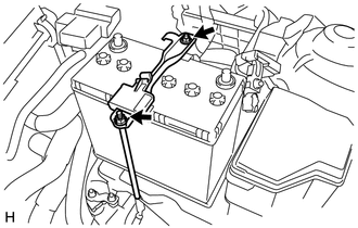
Loosen the 2 nuts and remove the battery clamp.
-
Remove the battery.
-
-
REMOVE BATTERY TRAY
-
Remove the battery tray.
-
-
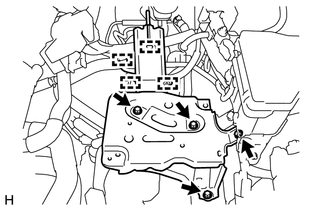
REMOVE BATTERY CARRIER (for LHD)
-
Disengage the 4 wire harness clamps and disconnect the wire harness from the battery carrier.
-
Remove the 4 bolts and battery carrier.
-
-
REMOVE BATTERY CARRIER (for RHD)

-
Disengage the 5 wire harness clamps and disconnect the wire harness from the battery carrier.
-
Remove the 4 bolts and battery carrier.
-
-
REMOVE FAN AND GENERATOR V BELT
-
REMOVE GENERATOR ASSEMBLY
-
DISCONNECT COMPRESSOR ASSEMBLY WITH PULLEY
-
Disconnect the compressor connector.
-
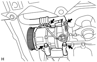
Remove the 4 bolts and the separate the compressor assembly with pulley.
Tech Tips
It is not necessary to completely remove the compressor. With the hoses connected to the compressor, hang the compressor on the vehicle body with a rope.
-
-
REMOVE EFI FUEL PIPE CLAMP
-
Remove the fuel pipe clamp.
-
-
DISCONNECT FUEL TUBE SUB-ASSEMBLY
-
Disconnect the fuel tube Click here.
-
-
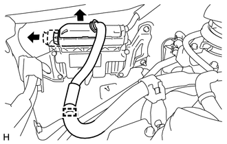
SEPARATE NO. 1 FUEL VAPOR FEED HOSE
-
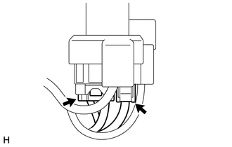
Disengage the No. 1 fuel vapor feed hose from the hose clamp.
-
Disconnect the No. 1 fuel vapor feed hose from the duty vacuum switching valve.
-
-
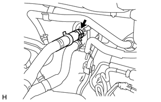
SEPARATE OUTLET HEATER WATER HOSE A
-
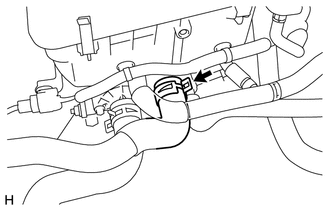
Disconnect the outlet heater water hose from the air conditioning unit.
-
-
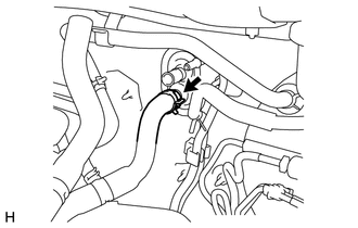
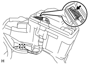
DISCONNECT INLET HEATER WATER HOSE A
-
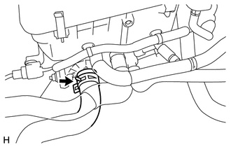
Disconnect the inlet heater water hose from the air conditioning unit.
-
-
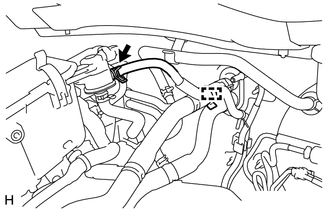
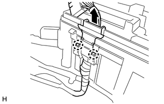
DISCONNECT BOOSTER VACUUM TUBE
-
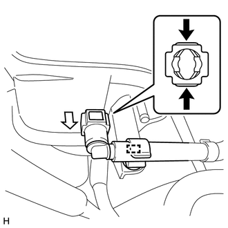
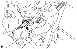
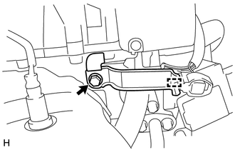
Pinch the retainer as illustrated, then pull the booster vacuum tube connector out of the intake manifold.
Text in Illustration 
Pinch 
Pull -
Disengage the clamp and disconnect the booster vacuum tube from the hose clamp.
-
-
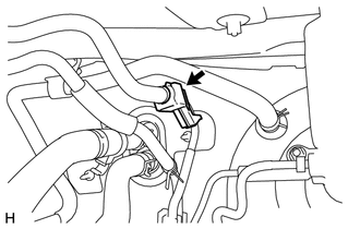
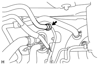
SEPARATE NO. 1 RADIATOR HOSE
-
Disconnect the No. 1 radiator hose from the cylinder head.
-
-
SEPARATE NO. 2 RADIATOR HOSE
-
Disconnect the No. 2 radiator hose from the water inlet.
-
-
REMOVE FRONT FLOOR CENTER BRACE
-
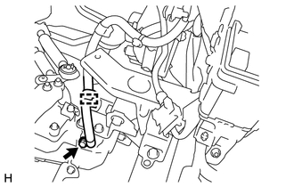
SEPARATE TAIL EXHAUST PIPE ASSEMBLY
-
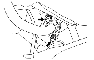
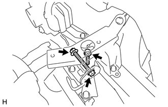
Remove the 2 bolts and 2 compression springs and separate the tail exhaust pipe from the front exhaust pipe.
-
-
SEPARATE NO. 2 HEATED OXYGEN SENSOR WIRE HARNESS
-
Disconnect the No. 2 heated oxygen sensor connector.
-
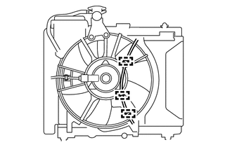
Disengage the 3 clamps and disconnect the No. 2 heated oxygen sensor wire from the fan shroud.
-
-
REMOVE FRONT EXHAUST PIPE ASSEMBLY
-
SEPARATE ENGINE WIRE
-
Disconnect the 2 connectors from the positive (+) battery terminal.
-
Disconnect the current sensor connector from the negative (-) battery terminal.
-
Slide the lever to disengage the lock, and separate the connector from the ECM.
-
Remove the engine junction block cover.
-
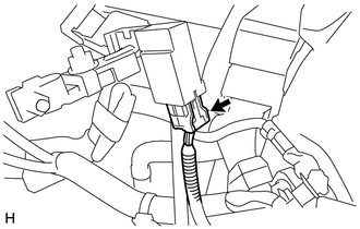
Disengage the wire harness clamp.
-
Disconnect the connector from the engine junction block.
-
Disengage the 2 claws and separate the wire harness from the junction block.
-
Disengage the wire harness clamp.
-
Remove the bolt and disconnect the ground wire from the transaxle.
-
Disconnect all the wire harnesses and connectors. Make sure that no wire harness is connected between the body and engine.
-
-
REMOVE RELEASE CYLINDER HEAT INSULATOR
-
SEPARATE CLUTCH RELEASE CYLINDER ASSEMBLY
-
SEPARATE TRANSMISSION CONTROL CABLE ASSEMBLY
-
REMOVE FRONT DRIVE SHAFT ASSEMBLY
-
REMOVE COLUMN HOLE COVER SILENCER SHEET
-
SEPARATE STEERING SLIDING YOKE SUB-ASSEMBLY
-
SEPARATE NO. 1 STEERING COLUMN HOLE COVER SUB-ASSEMBLY
-
REMOVE ENGINE ASSEMBLY WITH TRANSAXLE
-
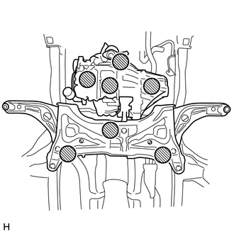
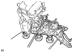
Place wooden blocks or plate lift attachments in the positions as shown in the illustration and set an engine lifter underneath the crossmember.
Text in Illustration 
Attachment Placement Positions Note
-
Place the wooden blocks or plate lift attachments so that the engine assembly with transaxle is level.
-
As the engine assembly with transaxle is very heavy, be sure to support it securely.
-
-
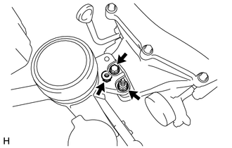
Remove the bolt and 2 nuts and separate the engine mounting insulator RH.
-
Remove the bolt, through bolt, nut and separate the engine mounting insulator LH.
-
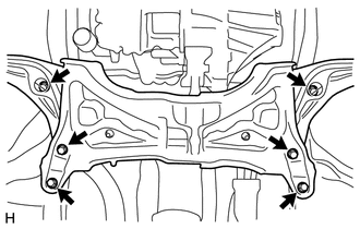
Remove the 6 bolts, the engine assembly with transaxle and the front suspension crossmember from the vehicle.
-
-
INSTALL ENGINE HANGERS
-
Remove the bolt and separate the wire harness clamp bracket.
-
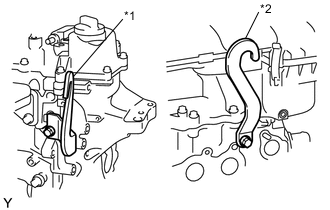
Text in Illustration *1 No. 1 Engine Hanger *2 No. 2 Engine Hanger Install the 2 engine hangers with the 2 bolts as shown in the illustration.
- Torque:
- 28 N*m { 286 kgf*cm, 21 ft.*lbf }
Tech Tips
Part Name Part No. No. 1 Engine Hanger 12281-40032 No. 2 Engine Hanger 12282-40010 Bolt 91671-80820
-
-
FIX ENGINE ASSEMBLY WITH TRANSAXLE
-
Using an engine sling device and a chain block, hold the engine assembly.
-
To enable removal of the engine assembly, adjust the positions of the plate lift attachments and set them in place.
Note
-
Set the plate lift attachments so that the engine assembly with transaxle is level.
-
Do not perform any procedure while the engine assembly is suspended because doing so may cause the engine assembly to drop, resulting in injury. However, the engine assembly needs to be suspended when it is installed to or removed from an engine stand.
-
-
Use a belt with a tighten mechanism or a rope to secure the engine assembly with transaxle to the engine lifter.
Note
-
Do not tighten the belt with a tightening mechanism or the rope any more than is necessary.
-
Set the engine assembly with transaxle so that it is horizontal.
-
-
-
REMOVE ENGINE WIRE
-
Disconnect all the wire harnesses and connectors. Make sure that no wire harnesses are connected to the engine.
-
-
REMOVE FLYWHEEL HOUSING SIDE COVER
-
REMOVE STARTER ASSEMBLY
-
REMOVE ENGINE ASSEMBLY
-
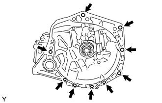
Remove the 9 bolts and engine assembly from the manual transaxle.
-
-
REMOVE CLUTCH COVER ASSEMBLY
-
REMOVE CLUTCH DISC ASSEMBLY
-
REMOVE FLYWHEEL SUB-ASSEMBLY
-
REMOVE ENGINE MOUNTING INSULATOR SUB-ASSEMBLY RH
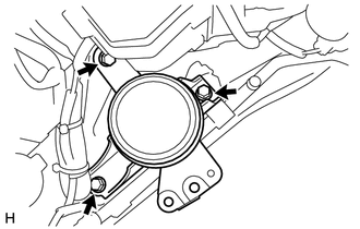
Tech Tips
Only perform this procedure when replacement of the engine mounting insulator RH is necessary.
-
Remove the 3 bolts and engine mounting insulator RH.
-
-
REMOVE ENGINE MOUNTING INSULATOR LH
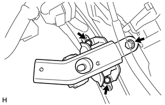
Tech Tips
Only perform this procedure when replacement of the engine mounting insulator LH is necessary.
-
Remove the 3 bolts and engine mounting insulator LH.
-