ENGINE ON-VEHICLE INSPECTION

PROCEDURE
-
INSPECT ENGINE IDLE SPEED
Note
-
Turn all the electrical systems and the A/C off.
-
Inspect the engine idle speed with the cooling fan off.
-
When checking the idle speed, the transaxle should be in neutral.
-
Warm up and stop the engine.
-
When using the intelligent tester:
-
Connect the intelligent tester to the DLC3.
-
Turn the ignition switch to ON and tester on.
-
Enter the following menus:
Powertrain / Engine and ECT / Data List / Engine Speed.
-
Inspect the engine idling speed.
Idling speed 720 to 820 rpm -
Fully depress the accelerator pedal.
-
Check the maximum speed.
Maximum speed 5150 to 5250 rpm -
Turn the ignition switch off.
-
Disconnect the intelligent tester from the DLC3.
-
-
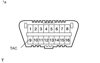
Text in Illustration *a Front view of DLC3 When not using the intelligent tester:
-
Install SST to terminal 9 (TAC) of DLC3, and then connect a tachometer.
- SST
- 09843-18040
Note
Examine the terminal numbers before connecting them. Connecting the wrong terminals can damage the engine.
-
Turn the ignition switch to ON.
-
Inspect the engine idling speed.
Idling speed 720 to 820 rpm -
Fully depress the accelerator pedal.
-
Check the maximum speed.
Maximum speed 5150 to 5250 rpm -
Turn the ignition switch off.
-
Disconnect the tachometer.
-
Remove SST from terminal 9.
-
-
-
INSPECT COMPRESSION (w/ DPF)
-
Warm up and stop the engine.
-
Disconnect the negative battery terminal.
-
Remove the 4 glow plugs Click here.
-
Disconnect the 4 connectors from the 4 injector assemblies.
-
Connect the negative battery terminal.
-
Crank the engine to remove foreign objects before measuring the compression.
-
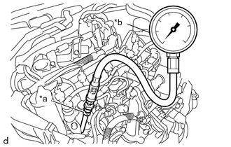
Text in Illustration *a SST (attachment) *b SST (Compression Gauge) Install the SST (attachment) into the glow plug hole.
- SST
- 09992-19015 ( 09992-10070, 09992-10100 )
- Torque:
- 13 N*m { 133 kgf*cm, 10 ft.*lbf }
-
Connect SST (compression gauge) to the SST (attachment).
- SST
- 09992-19015 ( 09992-10010, 09992-10020 )
-
While cranking the engine, measure the compression pressure.
Compression pressure 2300 kPa (23.5 kgf/cm2, 334 psi) Minimum pressure 2050 kPa (20.9 kgf/cm2, 297 psi) Difference between each cylinder 500 kPa (5.0 kgf/cm2, 71 psi) or less Note
-
Use a fully-charged battery so that the engine speed can be increased to 250 rpm or more.
-
Inspect the other cylinders in the same way.
-
Measure the compression pressure in as short a time as possible.
If the cylinder compression is low, pour a small amount of engine oil into the cylinder through the glow plug hole, and then inspect it again.
Tech Tips
-
If adding oil increases the compression, the piston rings and/or cylinder bore may be worn or damaged.
-
If the pressure stays low, a valve may be stuck or seated improperly, or there may be leakage from the gasket.
-
-
Remove the SST (compression gauge and attachment).
-
Disconnect the cable from the negative battery terminal.
-
Connect the 4 connectors to the 4 injector assemblies.
-
Install the 4 glow plugs Click here.
-
-
INSPECT COMPRESSION (w/o DPF)
-
Warm up and stop the engine.
-
Disconnect the negative battery terminal.
-
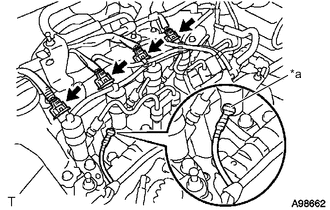
Text in Illustration *a Vinyl Tape Remove the 4 glow plugs Click here.
Note
In order to avoid shorting the circuit of the wire harness connected to the glow plug No. 1 connector, wind vinyl tape around the wire harness terminal portion.
-
Disconnect the 4 connectors from the 4 injector assemblies.
-
Connect the negative battery terminal.
-
Crank the engine to remove foreign objects before measuring the compression.
-
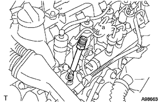
Text in Illustration *a SST (attachment) Install the SST (attachment) into the glow plug hole.
- SST
- 09992-19015 ( 09992-10070, 09992-10100 )
- Torque:
- 13 N*m { 133 kgf*cm, 10 ft.*lbf }
-
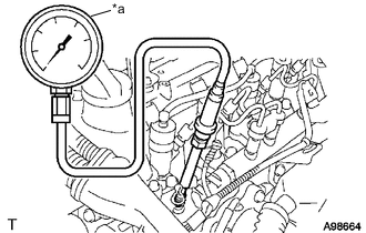
Text in Illustration *a SST (Compression Gauge) Connect SST (compression gauge) to the SST (attachment).
- SST
- 09992-19015 ( 09992-10010, 09992-10020 )
-
While cranking the engine, measure the compression pressure.
Compression pressure 2300 kPa (23.5 kgf/cm2, 334 psi) Minimum pressure 2050 kPa (20.9 kgf/cm2, 297 psi) Difference between each cylinder 500 kPa (5.0 kgf/cm2, 71 psi) or less Note
-
Use a fully-charged battery so that the engine speed can be increased to 250 rpm or more.
-
Inspect the other cylinders in the same way.
-
Measure the compression pressure in as short a time as possible.
If the cylinder compression is low, pour a small amount of engine oil into the cylinder through the glow plug hole, and then inspect it again.
Tech Tips
-
If adding oil increases the compression, the piston rings and/or cylinder bore may be worn or damaged.
-
If the pressure stays low, a valve may be stuck or seated improperly, or there may be leakage from the gasket.
-
-
Remove the SST (compression gauge and attachment).
-
Disconnect the cable from the negative battery terminal.
-
Connect the 4 connectors to the 4 injector assemblies.
-
Install the 4 glow plugs Click here.
-