PROCEDURE
- Click here
INSTALL CAMSHAFT TIMING SPROCKET ASSEMBLY
-
Apply engine oil to the camshaft timing sprocket assembly installation portion of the camshaft.
-
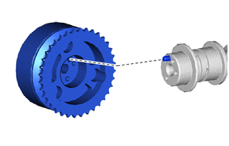
Insert the knock pin on the camshaft end into the knock pin hole in the camshaft timing sprocket assembly.
Note:
-
After insertion, gently rotate the camshaft timing sprocket assembly and check that the straight pin is securely inserted.
-
Because the tip of the camshaft straight pin may damage the seal surface of the camshaft timing sprocket assembly resulting in an improper seal, do not press forcefully on the camshaft timing sprocket assembly.
-
-
Temporarily install the camshaft timing sprocket assembly with the bolt.
-
Make sure that the camshaft timing sprocket assembly is locked.
-
- Click here
INSTALL CAMSHAFT
-
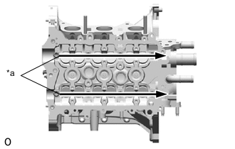
Apply engine oil to the cams of each camshaft, the journals of the cylinder head sub-assembly and the top of each valve lifter.
Table 1. Text in Illustration *a Apply Engine Oil -
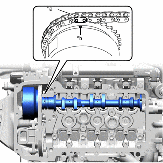
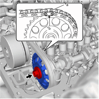
Align the paint make of the timing chain plate with the timing mark of the camshaft timing sprocket assembly and install the chain sub-assembly.
Table 2. Text in Illustration *a Paint Mark *b Timing Mark
-
- Click here
INSTALL NO. 2 CAMSHAFT
-
Set the No. 2 camshaft onto the cylinder head sub-assembly.
-
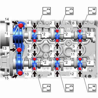
Place the No. 1 camshaft bearing cap and 6 No. 2 camshaft bearing caps and tighten the bolts to the specified torque in the sequence shown in the illustration.
Table 3. Text in Illustration *1 No. 1 Camshaft Bearing Cap *2 No. 2 Camshaft Bearing Cap No. 1 camshaft bearing cap 15 N*m 153 kgf*cm 11 ft.*lbf No. 2 camshaft bearing cap 13 N*m 127 kgf*cm 9 ft.*lbf Note:
-
Install the camshaft bearing caps with the front marks facing the front of the engine.
-
Install the bolts to the correct positions by referring to the numbers inscribed on the bolts and the following table.
Table 4. Installation Position of No. 2 Bearing Cap Installation Position Inscribed No. Intake No. 1 cylinder I2 Intake No. 2 cylinder I3 Intake No. 3 cylinder I4 Exhaust No. 1 cylinder E2 Exhaust No. 2 cylinder E3 Exhaust No. 3 cylinder E4 -
-
- Click here
INSTALL CAMSHAFT TIMING GEAR
-
Align the paint mark of the chain plate with the timing mark of the camshaft timing gear and install the chain sub-assembly.
Table 5. Text in Illustration *a Paint Mark *b Timing Mark -
Install the camshaft timing gear to the No. 2 camshaft with the knock pin aligned with the knock pin hole.
-
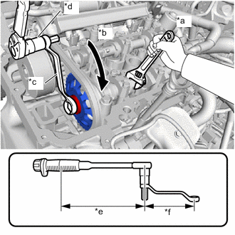
Using a wrench, hold the hexagonal portion of the No. 2 camshaft.
Table 6. Text in Illustration *a Hold *b Turn *c 12 x 14 mm Short Offset Wrench *d 12 mm Hexagon Socket Wrench *e Fulcrum Length of Torque Wrench *f Fulcrum Length of 12 x 14 mm Short Offset Wrench -
Using a 12 x 14 mm short offset wrench and 12 mm hexagon socket wrench, fully tighten the bolt.
Specified tightening torque 47 N*m 479 kgf*cm 35 ft.*lbf Tip:
-
Calculate the torque wrench reading when changing the fulcrum length of the torque wrench or 12 x 14 mm short offset wrench (Click here).
-
When using a 12 x 14 mm short offset wrench (fulcrum length of 125 mm (4.92 in.) + 12 mm hexagon socket wrench + torque wrench (fulcrum length of 260 mm (10.24 in.)): 32 N*m (323kgf*cm, 23 ft.*lbf).
-
-
- Click here
TIGHTEN CAMSHAFT TIMING SPROCKET ASSEMBLY
-
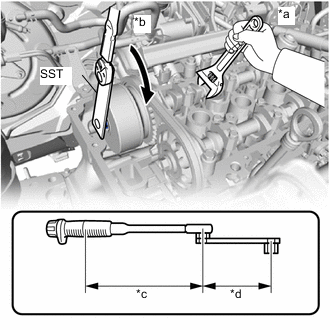
Using a wrench, hold the hexagonal portion of the camshaft.
Table 7. Text in Illustration *a Hold *b Turn *c Fulcrum Length of Torque Wrench *d Fulcrum Length of SST -
Using SST, fully tighten the bolt.
09249-37010 Specified tightening torque 47 N*m 479 kgf*cm 35 ft.*lbf Tip:
-
Calculate the torque wrench reading when changing the fulcrum length of the torque wrench (Click here).
-
When using SST (fulcrum length of 100 mm (3.94 in.)) + torque wrench (fulcrum length of 260 mm (10.24 in.)): 34 N*m (347 kgf*cm, 25 ft.*lbf).
-
-
- Click here
INSTALL TIGHT PLUG
-
Remove the 3 mm hexagon wrench from the No. 1 chain tensioner assembly.
-
Clean and degrease the threads of the tight plug and threaded tight plug hole of the timing chain cover sub-assembly.
-
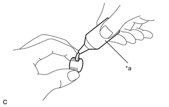
Adhesive to the threads of the tight plug.
Table 8. Text in Illustration *a Adhesive Adhesive Toyota Genuine Adhesive 1324, Three Bond 1324 or equivalent Note:To prevent contamination by foreign matter, install immediately after applying adhesive.
-
Using an 8 mm socket hexagon wrench, install the tight plug to the timing chain cover sub-assembly.
15 N*m 153 kgf*cm 11 ft.*lbf Note:Do not start the engine for at least 1 hour after installation.
-
- Click here
INSPECT VALVE CLEARANCE
- Click here
ADJUST VALVE CLEARANCE
- Click here
INSTALL CYLINDER HEAD COVER GASKET
- Click here
INSTALL CYLINDER HEAD COVER SUB-ASSEMBLY
- Click here
CONNECT ENGINE WIRE
-
Connect the engine wire to the cylinder head cover sub-assembly.
-
- Click here
CONNECT DUTY VACUUM SWITCHING VALVE
-
Connect the duty vacuum switching valve to the cylinder head cover sub-assembly with the bolt.
8.8 N*m 90 kgf*cm 78 in.*lbf
-
- Click here
INSTALL NO. 1 IGNITION COIL
- Click here
INSTALL AIR CLEANER FILTER ELEMENT SUB-ASSEMBLY
-
Install the air cleaner filter element sub-assembly to the cylinder head cover sub-assembly.
-
- Click here
INSTALL AIR CLEANER CAP SUB-ASSEMBLY
-
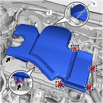
Temporarily set the air cleaner cap sub-assembly on the air cleaner cap support, No. 2 ventilation hose, and grommet.
Table 9. Text in Illustration *1 No. 2 Ventilation Hose *2 Air Cleaner Cap Support *a Stopper -
Insert the air cleaner cap sub-assembly into the air cleaner cap support.
Note:Securely insert the air cleaner cap sub-assembly until the stopper makes contact.
-
Insert the air cleaner cap sub-assembly into the No. 2 ventilation hose and grommet.
-
Secure the No. 2 ventilation hose with the hose clip.
-
Secure the air cleaner cap sub-assembly with the 4 clamp hooks.
-
- Click here
INSTALL INLET NO. 1 AIR CLEANER
-
Install the inlet No. 1 air cleaner to the cylinder head cover sub-assembly.
-
Install the inlet No. 1 air cleaner to the grommet.
-
- Click here
INSPECT ENGINE OIL LEVEL
- Click here
INSPECT FOR OIL LEAK