VALVE CLEARANCE ADJUSTMENT
PROCEDURE
-
REMOVE INLET NO. 1 AIR CLEANER
-
REMOVE AIR CLEANER CAP SUB-ASSEMBLY
-
REMOVE AIR CLEANER FILTER ELEMENT SUB-ASSEMBLY
-
REMOVE NO. 1 IGNITION COIL
-
SEPARATE DUTY VACUUM SWITCHING VALVE
-
SEPARATE ENGINE WIRE
-
REMOVE CYLINDER HEAD COVER SUB-ASSEMBLY
-
REMOVE CYLINDER HEAD COVER GASKET
-
SET NO. 1 CYLINDER TO TDC/EXHAUST
-
INSPECT VALVE CLEARANCE
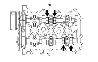
Text in Illustration *a Intake Side *b Exhaust Side
-
Check only the valves indicated.
-
Using a feeler gauge, measure the clearance between the valve lifter and camshaft.
Valve clearance (Cold) Intake side 0.145 to 0.235 mm (0.00571 to 0.00925 in.) Exhaust side 0.275 to 0.365 mm (0.01083 to 0.01437 in.) Inspectable Valve w/ No. 1 Cylinder at TDC/Exhaust Measurement Position No. 1 Cylinder No. 2 Cylinder No. 3 Cylinder Intake Side - ○ - Exhaust Side - - ○ Note
Insert the feeler gauge from the spark plug side (center).
-
Record any out-of-specification valve clearance measurements. They will be used later to determine the required replacement valve lifters.
-
-
Turn the crankshaft 1 revolution (360°).
-
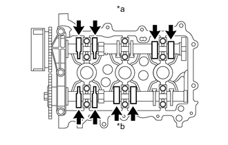
Text in Illustration *a Intake Side *b Exhaust Side Check only the valves indicated.
-
Using a feeler gauge, measure the clearance between the valve lifter and camshaft.
Valve clearance (Cold) Intake side 0.145 to 0.235 mm (0.00571 to 0.00925 in.) Exhaust side 0.275 to 0.365 mm (0.01083 to 0.01437 in.) Inspectable Valve w/ No. 1 Cylinder at TDC Measurement Position No. 1 Cylinder No. 2 Cylinder No. 3 Cylinder Intake Side ○ - ○ Exhaust Side ○ ○ - Note
Insert the feeler gauge from the spark plug side (center).
-
Record any out-of-specification valve clearance measurements. They will be used later to determine the required replacement valve lifters.
-
-
-
ADJUST VALVE CLEARANCE
-
Remove the camshaft and No. 2 camshaft Click here.
-
Remove the valve lifters Click here.
-
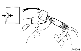
Using a micrometer, measure the thickness of the removed valve lifters.
-
Calculate the thickness of a new valve lifter so that the valve clearance comes within the specified value.
A Thickness of new lifter B Thickness of used lifter C Measured valve clearance Valve clearance Intake A = B + (C - 0.18 mm (0.0071 in.)) Exhaust A = B + (C - 0.31 mm (0.0122 in.)) Tech Tips
-
Select a new valve lifter with a thickness as close to the calculated values as possible.
-
Valve lifters are available in 29 sizes in increments of 0.020 mm (0.0008 in.), from 5.12 to 5.68 mm (0.2016 to 0.2236 in.).
-
Refer to the following Valve Lifter Selection Charts.
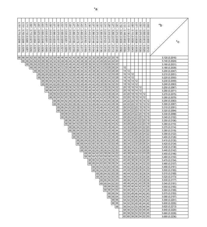
Text in Illustration *a Valve Lifter Selection Chart (Intake) *b Measured Valve Clearance mm (in.) *c Installed Valve Lifter Thickness mm (in.) - - 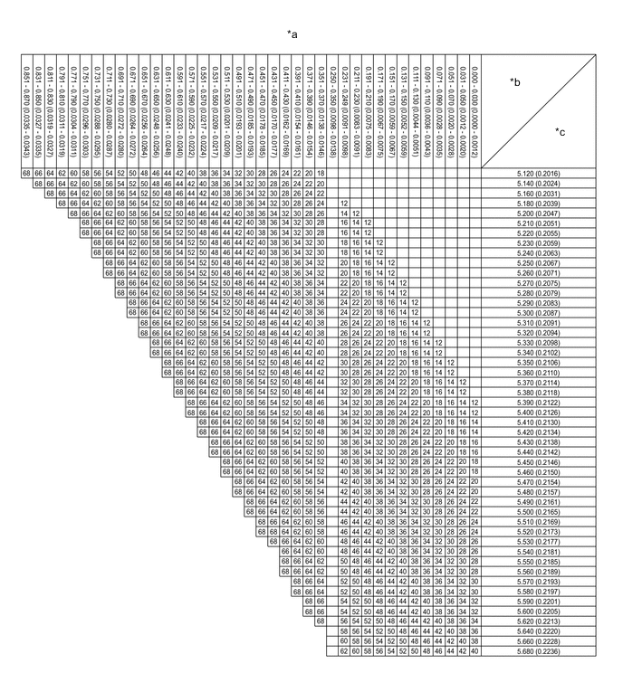
Text in Illustration *a Valve Lifter Selection Chart (Exhaust) *b Measured Valve Clearance mm (in.) *c Installed Valve Lifter Thickness mm (in.) - - Tech Tips
New Valve lifter Thickness mm (in.) Lifter No. Thickness Lifter No. Thickness Lifter No. Thickness 12 5.12 (0.2016) 32 5.32 (0.2094) 52 5.52 (0.2173) 14 5.14 (0.2024) 34 5.34 (0.2102) 54 5.54 (0.2181) 16 5.16 (0.2031) 36 5.36 (0.2110) 56 5.56 (0.2189) 18 5.18 (0.2039) 38 5.38 (0.2118) 58 5.58 (0.2197) 20 5.20 (0.2047) 40 5.40 (0.2126) 60 5.60 (0.2205) 22 5.22 (0.2055) 42 5.42 (0.2134) 62 5.62 (0.2213) 24 5.24 (0.2063) 44 5.44 (0.2142) 64 5.64 (0.2220) 26 5.26 (0.2071) 46 5.46 (0.2150) 66 5.66 (0.2228) 28 5.28 (0.2079) 48 5.48 (0.2157) 68 5.68 (0.2236) 30 5.30 (0.2087) 50 5.50 (0.2165) - - -
-
Install the valve lifters Click here.
-
Install the camshaft and No. 2 camshaft Click here.
-
-
INSTALL CYLINDER HEAD COVER GASKET
-
INSTALL CYLINDER HEAD COVER SUB-ASSEMBLY
-
CONNECT ENGINE WIRE
-
CONNECT DUTY VACUUM SWITCHING VALVE
-
INSTALL NO. 1 IGNITION COIL
-
INSTALL AIR CLEANER FILTER ELEMENT SUB-ASSEMBLY
-
INSTALL AIR CLEANER CAP SUB-ASSEMBLY
-
INSTALL INLET NO. 1 AIR CLEANER
-
INSPECT FOR OIL LEAK