CYLINDER HEAD GASKET INSTALLATION
PROCEDURE
-
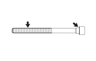
INSPECT CYLINDER HEAD SET BOLT
-
INSTALL CYLINDER HEAD GASKET
-
Inspect and clean the installation hole of the cylinder block sub-assembly cylinder head set bolt.
-
Clean and degrease the lower surface of the cylinder head sub-assembly and upper surface of the cylinder block sub-assembly.
-
Apply seal packing to a new cylinder head gasket as shown in the illustration.
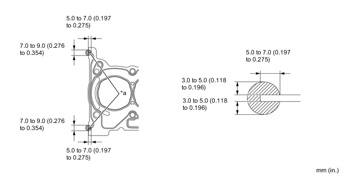
Text in Illustration *a Seal Packing - - Seal packing Toyota Genuine Seal Packing Black, Three Bond 1207B or equivalent Note
-
Apply seal packing to the bead on the cylinder head gasket.
-
Install the cylinder head within 3 minutes and tighten the bolts within 15 minutes after applying seal packing.
-
Do not start the engine for at least 2 hours after installation.
-
-
Place the cylinder head gasket onto the cylinder block sub-assembly.
-
-
INSTALL CYLINDER HEAD SUB-ASSEMBLY
-
Place the cylinder head sub-assembly on the cylinder block sub-assembly.
-
Install the 8 plate washers to the cylinder head sub-assembly.
Note
Do not drop the washers into the cylinder head sub-assembly.
-
Apply engine oil to the threads and seating surface of each cylinder head bolt.
-
Temporarily install the 8 cylinder head set bolts to the cylinder head sub-assembly.
-
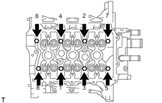
Using an 8 mm bi-hexagon wrench, uniformly tighten the 8 cylinder head bolts in several steps in the sequence shown in the illustration.
- Torque:
- 32 N*m { 326 kgf*cm, 24 ft.*lbf }
-
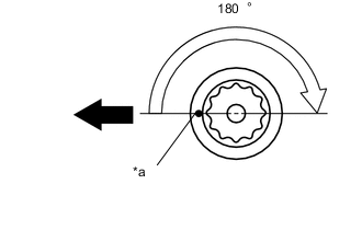
Text in Illustration *a Paint Mark 
Engine Front Mark the front of each cylinder head bolt with paint.
-
Tighten the cylinder head bolts by an additional 180° as shown in the illustration.
-
Check that the paint marks are now at a 180° angle from the front.
-
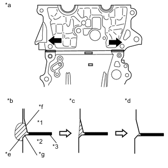
Text in Illustration *1 Cylinder Head Sub-assembly *2 Cylinder Block Sub-assembly *3 Cylinder Head Gasket *a Direction to wipe off *b Before wiping with scraper *c After wiping with scraper *d After wiping with cloth *e Seal packing *f Chamfer of cylinder head sub-assembly *g Chamfer of cylinder block sub-assembly After wiping off the excess seal packing with a scraper, use a piece of cloth to wipe off any seal packing that remains on the chamfered portions of the cylinder block sub-assembly and cylinder head sub-assembly.
Note
-
Using the cloth, wipe parallel to the upper surface of the cylinder block sub-assembly, wiping from the inner side toward the outer side.
-
When wiping with the cloth, make sure that seal packing does not enter the bolt holes of the cylinder head sub-assembly or cylinder block sub-assembly.
-
Do not wipe off too much seal packing, because the edge of the cylinder head gasket must not be visible.
-
Do not allow seal packing to adhere to the chamfered portions of the cylinder block sub-assembly or cylinder head sub-assembly.
-
-
-
INSTALL CAMSHAFT
-
INSTALL NO. 2 CAMSHAFT
-
INSTALL CAMSHAFT BEARING CAP
-
INSTALL CAMSHAFT TIMING SPROCKET ASSEMBLY
-
INSTALL TIMING CHAIN GUIDE
-
INSTALL CHAIN SUB-ASSEMBLY
-
INSTALL TIMING CHAIN TENSION ARM
-
INSTALL NO. 1 CHAIN TENSIONER ASSEMBLY
-
INSTALL TIMING CHAIN COVER OIL SEAL
-
INSTALL TIMING CHAIN COVER SUB-ASSEMBLY
-
INSTALL CRANKSHAFT PULLEY
-
INSTALL OIL PAN SUB-ASSEMBLY
-
INSTALL CYLINDER HEAD COVER GASKET
-
INSTALL CYLINDER HEAD COVER SUB-ASSEMBLY
-
INSTALL V-RIBBED BELT TENSIONER ASSEMBLY
-
INSTALL NO. 1 IGNITION COIL
-
INSTALL CRANKSHAFT POSITION SENSOR
-
INSTALL CAMSHAFT TIMING OIL CONTROL VALVE O-RING
-
INSTALL CAMSHAFT TIMING OIL CONTROL VALVE ASSEMBLY
-
INSTALL OIL LEVEL DIPSTICK GUIDE O-RING
-
INSTALL OIL LEVEL DIPSTICK GUIDE
-
INSTALL OIL LEVEL DIPSTICK SUB-ASSEMBLY
-
INSTALL WATER BY-PASS PIPE
-
INSTALL INLET EGR GASKET
-
INSTALL EXHAUST MANIFOLD TO HEAD GASKET
-
INSTALL EXHAUST MANIFOLD
-
INSTALL MANIFOLD STAY
-
INSTALL EGR VALVE GASKET
-
INSTALL EGR VALVE ASSEMBLY
-
INSTALL NO. 2 INTAKE MANIFOLD TO HEAD GASKET
-
INSTALL NO. 1 INTAKE MANIFOLD INSULATOR
-
INSTALL NO. 1 INTAKE MANIFOLD TO HEAD GASKET
-
INSTALL INTAKE MANIFOLD
-
INSTALL WIRE HARNESS CLAMP BRACKET
-
INSTALL FUEL TUBE SUB-ASSEMBLY
-
INSTALL EFI FUEL PIPE CLAMP
-
INSTALL THROTTLE BODY GASKET
-
INSTALL THROTTLE WITH MOTOR BODY ASSEMBLY
-
INSTALL AIR CLEANER CAP SUPPORT
-
INSTALL NO. 2 WATER BY-PASS HOSE
-
INSTALL INLET HEATER WATER HOSE A
-
INSTALL NO. 2 WATER BY-PASS HOSE
-
INSTALL NO. 1 WATER BY-PASS HOSE
-
INSTALL ENGINE HANGER
-
REMOVE ENGINE STAND