SFI SYSTEM Cooling System
DESCRIPTION
The fuel pump circuit consists of the ECM, fuel pump and fuel pump control ECU (which operates the fuel pump). Based on the engine output, the ECM determines the fuel pump speed. The speed is then converted to a duty signal and sent to the fuel pump control ECU. Based on the signal sent from the ECM, the fuel pump control ECU adjust the fuel pump operation speed.
CAUTION / NOTICE / HINT
Note
Inspect the fuses for circuits related to this system before performing the following procedure.
PROCEDURE
-
PERFORM ACTIVE TEST USING GTS (CONTROL THE FUEL PUMP / SPEED)
-
Connect the GTS to the DLC3.
-
Turn the engine switch on (IG).
-
Turn the GTS on.
-
Enter the following menus: Powertrain / Engine / Active Test / Control the Fuel Pump / Speed.
-
Check whether the fuel pump operating sound occurs when performing the Active Test on the GTS.
Result Result Proceed to Fuel pump operating sound does not occur A Fuel pump operating sound occurs B
B 
PROCEED TO NEXT SUSPECTED AREA SHOWN IN PROBLEM SYMPTOMS TABLE Click here
A 
-
-
INSPECT CHARGE WATER COOLER PUMP
-
Inspect the fuel pump.
Result Proceed to OK NG
NG
REPLACE CHARGE WATER COOLER PUMP Click here
OK
-
-
CHECK TERMINAL VOLTAGE (FPC TERMINAL VOLTAGE)
-
Turn the engine switch on (IG).
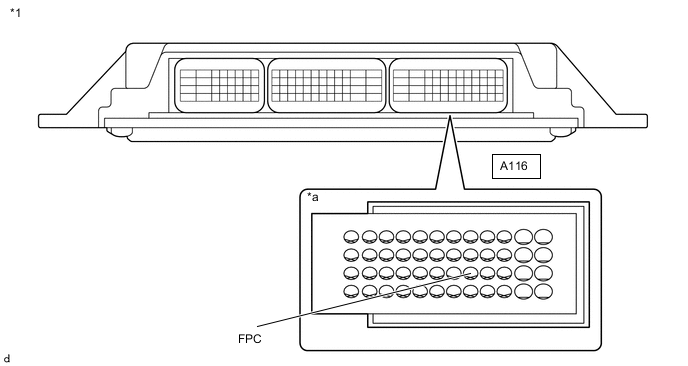
*a Component with harness connected
(ECM)
- - -
Measure the voltage according to the value(s) in the table below.
Standard Voltage Tester Connection Switch Condition Specified Condition A116-32 (FPC) - Body ground Engine switch on (IG) 11 to 14 V Result Proceed to OK NG
NG 
INSPECT C/OPN RELAY Click here
OK
-
-
CHECK TERMINAL VOLTAGE (POWER SOURCE OF C/OPN RELAY)
-
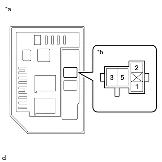
*a No. 2 Engine Room Relay Block Assembly *b C/OPN Relay Holder Remove the C/OPN relay from the No. 2 engine room relay block assembly.
-
Measure the voltage according to the value(s) in the table below.
Standard Voltage Tester Connection Condition Specified Condition 5 (C/OPN relay holder) - Body ground Always 11 to 14 V Result Proceed to OK NG
NG
REPAIR OR REPLACE HARNESS OR CONNECTOR
OK
-
-
CHECK HARNESS AND CONNECTOR (C/OPN RELAY - FUEL SUCTION TUBE WITH PUMP AND GAUGE ASSEMBLY)
-
Remove the C/OPN relay from the No. 2 engine room relay block assembly.
-
Disconnect the K17 fuel suction tube with pump and gauge assembly connector.
-
Disconnect the A115 charge water cooler pump connector.
-
Measure the resistance according to the value(s) in the table below.
Standard Resistance Tester Connection Condition Specified Condition 3 (C/OPN relay holder) - K17-4 Always Below 1 Ω 3 (C/OPN relay holder) - A115-1 Always Below 1 Ω 3 (C/OPN relay holder) or K17-4 - Body ground and other terminals Always 10 kΩ or higher 3 (C/OPN relay holder) or A115-1 - Body ground and other terminals Always 10 kΩ or higher Result Proceed to OK NG
NG
REPAIR OR REPLACE HARNESS OR CONNECTOR
OK
-
-
CHECK HARNESS AND CONNECTOR (CHARGE WATER COOLER PUMP - BODY GROUND)
-
Disconnect the A115 charge water cooler pump connector.
-
Measure the resistance according to the value(s) in the table below.
Standard Resistance Tester Connection Condition Specified Condition A115-2 - Body ground Always Below 1 Ω Result Proceed to OK NG
OK
REPLACE ECM Click here
NG
REPAIR OR REPLACE HARNESS OR CONNECTOR
-
-
INSPECT C/OPN RELAY
-
Inspect the C/OPN relay.
Result Proceed to OK NG
NG
REPLACE C/OPN RELAY
OK
-
-
CHECK TERMINAL VOLTAGE (POWER SOURCE OF C/OPN RELAY)
-
*a No. 2 Engine Room Relay Block Assembly *b C/OPN Relay Holder Remove the C/OPN relay from the No. 2 engine room relay block assembly.
-
Measure the voltage according to the value(s) in the table below.
Standard Voltage Tester Connection Condition Specified Condition 5 (C/OPN relay holder) - Body ground Always 11 to 14 V Result Proceed to OK NG
OK
REPAIR OR REPLACE HARNESS OR CONNECTOR
NG
CHECK ECM POWER SOURCE CIRCUIT Click here
-