SFI SYSTEM Cranking Holding Function Circuit
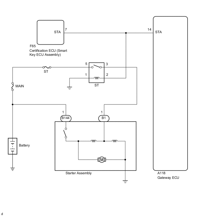
WIRING DIAGRAM
CAUTION / NOTICE / HINT
Note
Inspect the fuses for circuits related to this system before performing the following procedure.
Tech Tips
Read freeze frame data using the GTS. The ECM records vehicle and driving condition information as freeze frame data the moment a DTC is stored. When troubleshooting, freeze frame data can help determine if the vehicle was moving or stationary, if the engine was warmed up or not, if the air fuel ratio was lean or rich, and other data from the time the malfunction occurred.
PROCEDURE
-
READ VALUE USING GTS (STARTER SIGNAL)
-
Connect the GTS to the DLC3.
-
Turn the engine switch on (IG).
-
Turn the GTS on.
-
Enter the following menus: Powertrain / Engine / Data List / Starter Signal.
-
According to the display on the GTS, read the Data List.
Standard Condition Starter Signal Engine switch on (IG) OFF Driving at 20 km/h (12.43 mph) or more (engine speed 1000 rpm or more) OFF Tech Tips
If the result of either of the above is not as specified, proceed to the next step with the engine switch on (IG), GTS connected and Data List item "Starter Signal" selected.
Result Proceed to OK NG Tech Tips
If the starter assembly operates continuously when the engine switch is turned to on (IG), proceed to the next step without reading the Data List item "Starter Signal".
OK 
CHECK FOR INTERMITTENT PROBLEMS Click here
NG 
-
-
INSPECT ST RELAY (CHECK FOR SHORT CIRCUIT)
-
Connect the GTS to the DLC3.
-
Turn the engine switch on (IG).
-
Turn the GTS on.
-
Enter the following menus: Powertrain / Engine / Data List / Starter Signal.
-
Remove the ST relay from the No. 1 engine room relay block.
-
According to the display on the GTS, read the Data List.
Result Result Proceed to The Data List item "Starter Signal" does not change from ON. A The Data List item "Starter Signal" changes from ON to OFF. B Tech Tips
When the result of the above inspection is "The Data List item "Starter Signal" does not change from ON", the ST relay is normal.
B 
CHECK HARNESS AND CONNECTOR (STA SIGNAL CIRCUIT) Click here
A
-
-
CHECK TERMINAL VOLTAGE (POWER SOURCE OF ST RELAY)
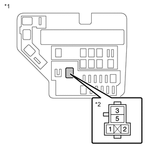
*1 No. 1 Engine Room Relay Block *2 ST Relay Holder Tech Tips
The purpose of this step is to check for ST relay terminal voltage under abnormal conditions.
-
Remove the ST relay from the No. 1 engine room relay block.
-
Turn the engine switch on (IG).
-
Measure the voltage between ST relay terminal 2 and body ground.
Tech Tips
-
Make a note of the measured voltage as it will be necessary for the inspecting the change in voltage in the next step. As the next step should be conducted under the same conditions, keep the engine switch on (IG) and do not install the ST relay.
-
If any voltage was measured with the engine switch on (IG), one of the following malfunctions is suspected:
-
Short to +B in the circuit of a connected ECU or the engine switch.
-
Short to +B in the wire harness.
-
Result Proceed to NEXT
NEXT
-
-
INSPECT NETWORK GATEWAY ECU (CHECK FOR SHORT CIRCUIT)
*1 No. 1 Engine Room Relay Block *2 ST Relay Holder
-
Disconnect the A118 network gateway ECU connector.
-
Measure the voltage between ST relay terminal 2 and body ground and compare it to the voltage measured in the previous step.
Result Result Proceed to The voltage between ST relay terminal 2 and body ground does not change when the connector is disconnected. A The voltage between ST relay terminal 2 and body ground changes when the connector is disconnected. B Tech Tips
If the voltage is the same before and after disconnecting the connector, the ECM is normal.
B
REPLACE NETWORK GATEWAY ECU Click here
A
-
-
CHECK HARNESS AND CONNECTOR
-
Remove the ST relay from the No. 1 engine room relay block.
-
Disconnect the F65 certification ECU (smart key ECU assembly) connector.
-
Disconnect the A118 network gateway ECU connector.
-
Measure the resistance according to the value(s) in the table below.
Standard Resistance Tester Connection Condition Specified Condition 2 (ST relay holder), F65-7 (STA) or A118-14 (STA) - Other terminals Always 10 kΩ or higher Result Proceed to OK NG
OK
CHECK ENTRY AND START SYSTEM
NG
REPAIR OR REPLACE HARNESS OR CONNECTOR (STA SIGNAL CIRCUIT)
-
-
CHECK HARNESS AND CONNECTOR (STA SIGNAL CIRCUIT)
-
Remove the ST relay from the No. 1 engine room relay block.
-
Disconnect the F65 certification ECU (smart key ECU assembly) connector.
-
Disconnect the A118 network gateway ECM connector.
-
Measure the resistance according to the value(s) in the table below.
Standard Resistance Tester Connection Condition Specified Condition A39-1 - A58-29 (STA) Always Below 1 Ω 2 (ST relay holder), F65-7 (STA), B69-9 (L), A53-4 (STA) or A58-29 (STA) - Body ground and other terminals*1 Always 10 kΩ or higher 2 (ST relay holder), F65-7 (STA), B69-9 (L), or A58-29 (STA) - Body ground and other terminals*2 Always 10 kΩ or higher Result Proceed to OK NG
OK
REPLACE ST RELAY
NG
REPAIR OR REPLACE HARNESS OR CONNECTOR (STA SIGNAL CIRCUIT)
-