SFI SYSTEM, Diagnostic DTC:P2127
| DTC Code | DTC Name |
|---|---|
| P2127 | Throttle / Pedal Position Sensor / Switch "E" Circuit Low |
DESCRIPTION
| DTC No. | Detection Item | DTC Detection Condition | Trouble Area | MIL | Memory |
|---|---|---|---|---|---|
| P2127 | Throttle / Pedal Position Sensor / Switch "E" Circuit Low | DTC Detection Condition
Enable Criteria
Malfunction Criteria
Diagnostic Mask
Monitor
Potential failure modes |
|
Comes on | DTC stored |
MONITOR DESCRIPTION
Two potentiometers are built into the throttle pedal unit in order to provide a throttle demand signal to the ECU. Note that the potentiometers operate on 5 volts.
CAUTION / NOTICE / HINT
Tech Tips
Read freeze frame data using the GTS. The ECM records vehicle and driving condition information as freeze frame data the moment a DTC is stored. When troubleshooting, freeze frame data can help determine if the vehicle was moving or stationary, if the engine was warmed up or not, if the air fuel ratio was lean or rich, and other data from the time the malfunction occurred.
PROCEDURE
-
READ VALUE USING GTS (ACCEL SENSOR OUT)
-
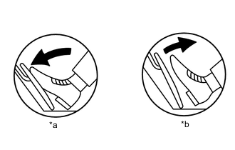
*a Fully Depressed *b Fully Released Connect the GTS to the DLC3.
-
Turn the engine switch on (IG).
-
Turn the GTS on.
-
Enter the following menus: Powertrain / Engine / Data List / Accel Sensor Out No.1 and Accel Sensor Out No.2.
-
Read the value displayed on the GTS.
Standard Voltage Accelerator Pedal Operation Accel Sensor Out No.1 Accel Sensor Out No.2 Difference between Accel Sensor Out No.1 and Accel Sensor Out No.2 Fully Released 0.5 to 1.1 V 1.2 to 2.0 V More than 0.02 V Fully Depressed 2.6 to 4.5 V 3.4 to 4.75 V Result Proceed to OK NG
OK 
CHECK FOR INTERMITTENT PROBLEMS Click here
NG 
-
-
CHECK HARNESS AND CONNECTOR (ACCELERATOR PEDAL SENSOR ASSEMBLY - ECM)
-
Disconnect the A36 accelerator pedal sensor assembly connector.
-
Disconnect the A116 ECM connector.
-
Measure the resistance according to the value(s) in the table below.
Standard Resistance Tester Connection Condition Specified Condition A36-6 (VPA) - A116-2 (VPA) Always Below 1 Ω A36-5 (EPA) - A116-10 (EPA) Always Below 1 Ω A36-4 (VCPA) - A116-18 (VCPA) Always Below 1 Ω A36-3 (VPA2) - A116-1 (VPA2) Always Below 1 Ω A36-2 (EPA2) - A116-46 (EPA2) Always Below 1 Ω A36-1 (VCP2) - A116-45 (VCP2) Always Below 1 Ω A36-6 (VPA) or A116-2 (VPA) - Body ground and other terminals Always 10 kΩ or higher A36-4 (VCPA) or A116-18 (VCPA) - Body ground and other terminals Always 10 kΩ or higher A36-3 (VPA2) or A116-1 (VPA2) - Body ground and other terminals Always 10 kΩ or higher A36-1 (VCP2) or A116-45 (VCP2) - Body ground and other terminals Always 10 kΩ or higher Result Proceed to OK NG
NG
REPAIR OR REPLACE HARNESS OR CONNECTOR
OK
-
-
CHECK TERMINAL VOLTAGE (POWER SOURCE OF ACCELERATOR PEDAL SENSOR ASSEMBLY)
-
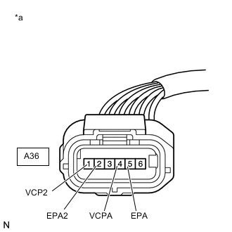
*a Front view or wire harness connector
(to Accelerator Pedal Sensor Assembly)
Disconnect the accelerator pedal sensor assembly connector.
-
Turn the engine switch on (IG).
-
Measure the voltage according to the value(s) in the table below.
Standard Voltage Tester Connection Switch Condition Specified Condition A36-4 (VCPA) - A36-5 (EPA) Engine switch on (IG) 4.5 to 5.5 V A36-1 (VCP2) - A36-2 (EPA2) Engine switch on (IG) 4.5 to 5.5 V Result Proceed to OK NG
NG
REPLACE ECM Click here
OK
-
-
REPLACE ACCELERATOR PEDAL SENSOR ASSEMBLY
-
Replace the accelerator pedal sensor assembly.
Result Proceed to NEXT
NEXT
-
-
CHECK WHETHER DTC OUTPUT RECURS (ACCELERATOR PEDAL SENSOR DTCS)
-
Connect the GTS to the DLC3.
-
Turn the engine switch on (IG).
-
Turn the GTS on.
-
Clear the DTCs.
-
Turn the engine switch off and wait for at least 30 seconds.
-
Turn the engine switch on (IG).
-
Turn the GTS on.
-
Enter the following menus: Powertrain / Engine / Trouble Codes.
-
Read the DTCs.
Result Result Proceed to DTC P2127 are output A DTC is not output B
A
REPLACE ECM Click here
B
END
-