SFI SYSTEM, Diagnostic DTC:P1108
| DTC Code | DTC Name |
|---|---|
| P1108 | Manifold Absolute Pressure Sensor AD Too High |
DESCRIPTION
| DTC No. | Detection Item | DTC Detection Condition | Trouble Area | MIL | Memory |
|---|---|---|---|---|---|
| P1108 | Manifold Absolute Pressure Sensor AD Too High | DTC Detection Condition
Enable Criteria
Malfunction Criteria
Diagnostic Mask
Monitor
Potential failure modes |
|
Comes on | DTC stored |
MONITOR DESCRIPTION
The ECM monitors the sensor voltage and uses this value to calculate the manifold absolute pressure. When the sensor output voltage deviates from the normal operating range, the ECM interprets this as a malfunction in the manifold pressure sensor and stores the DTC.
Example:
When the sensor output voltage is less than 0.5 V, or higher than 4.5 V for 0.5 seconds or more, the ECM stores the DTC.
CAUTION / NOTICE / HINT
Tech Tips
Read freeze frame data using the GTS. The ECM records vehicle and driving condition information as freeze frame data the moment a DTC is stored. When troubleshooting, freeze frame data can help determine if the vehicle was moving or stationary, if the engine was warmed up or not, if the air fuel ratio was lean or rich, and other data from the time the malfunction occurred.
PROCEDURE
-
READ VALUE USING GTS (MAP)
-
Connect the GTS to the DLC3.
-
Turn the engine switch on (IG).
-
Turn the GTS on.
-
Enter the following menus: Powertrain / Engine / Data List / MAP.
-
Read the MAP value.
OK Same value as the actual atmospheric pressure Tech Tips
-
Standard atmospheric pressure is 101 kPa(abs) [758 mmHg(abs)]. For every 100 m (328 ft.) increase in altitude, atmospheric pressure drops by approximately 1 kPa (7.5 mmHg). The pressure also varies due to the weather (high atmospheric pressure, low atmospheric pressure).
-
Also, check "Atmosphere Pressure" in the Data List.
Result Proceed to OK NG -
OK 
CHECK FOR INTERMITTENT PROBLEMS Click here
NG 
-
-
CHECK TERMINAL VOLTAGE (POWER SOURCE OF VACUUM SENSOR (MAINFOLD ABSOLUTE PRESSURE SENSOR))
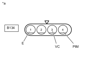
*a Front view of wire harness connector
(to Vacuum Sensor (Mainfold Absolute Pressure Sensor))
-
Disconnect the vacuum sensor (manifold absolute pressure sensor) connector.
-
Turn the engine switch on (IG).
-
Measure the voltage according to the value(s) in the table below.
Standard Voltage Tester Connection Switch Condition Specified Condition B134-3 (VC) - B134-1 (E) Engine switch on (IG) 4.5 to 5.5 V B134-4 (PIM) - B134-1 (E) Engine switch on (IG) 4.0 to 5.0 V Result Proceed to OK NG
NG 
CHECK HARNESS AND CONNECTOR (ECM - VACUUM SENSOR (MAINFOLD ABSOLUTE PRESSURE SENSOR)) Click here
OK
-
-
REPLACE MANIFOLD ABSOLUTE PRESSURE SENSOR
-
Replace the manifold absolute pressure sensor.
Result Proceed to NEXT
NEXT
-
-
CHECK WHETHER DTC OUTPUT RECURS (DTC P1108)
-
Connect the GTS to the DLC3.
-
Turn the engine switch on (IG).
-
Turn the GTS on.
-
Clear the DTC.
-
Turn the engine switch off and wait for at least 30 seconds.
-
Turn the engine switch on (IG).
-
Turn the GTS on.
-
Enter the following menus: Powertrain / Engine / Trouble Codes.
-
Read the DTCs.
Result Result Proceed to DTC is not output A DTC P0108 is output B
A
END
B
REPLACE ECM Click here
-
-
CHECK HARNESS AND CONNECTOR (ECM - VACUUM SENSOR (MAINFOLD ABSOLUTE PRESSURE SENSOR))
-
Disconnect the B142 ECM connector.
-
Disconnect the B134 vacuum sensor (mainfold absolute pressure sensor) connector.
-
Disconnect the A117 mass air flow meter connector.
-
Measure the resistance according to the value(s) in the table below.
Standard Resistance Tester Connection Condition Specified Condition B142-45 (VCPM) - B134-3 (VC) Always Below 1 Ω B142-4 (PIM) - B134-4 (PIM) Always Below 1 Ω B142-9 (E2) - B134-1 (E) Always Below 1 Ω B142-45 (VCPM) or B134-3 (VC) - Body ground and other terminals Always 10 kΩ or higher B142-4 (PIM) or B134-4 (PIM) - Body ground and other terminals Always 10 kΩ or higher B142-9 (E2) or B134-1 (E) - Body ground and other terminals Always 10 kΩ or higher Result Proceed to OK NG
OK
REPLACE ECM Click here
NG
REPAIR OR REPLACE HARNESS OR CONNECTOR
-