SFI SYSTEM, Diagnostic DTC:P0562
| DTC Code | DTC Name |
|---|---|
| P0562 | System Voltage Low |
DESCRIPTION
| DTC No. | Detection Item | DTC Detection Condition | Trouble Area | MIL | Memory |
|---|---|---|---|---|---|
| P0562 | System Voltage Low | DTC Detection Condition
Enable Criteria
Malfunction Criteria
Diagnostic Mask
Monitor
Potential failure modes |
|
Comes on | DTC stored |
MONITOR DESCRIPTION
With a battery and alternator functioning as normal the system voltage for a running engine should be around 14 V. The ECM monitors this and will diagnose if the voltage is too high or too low.
WIRING DIAGRAM
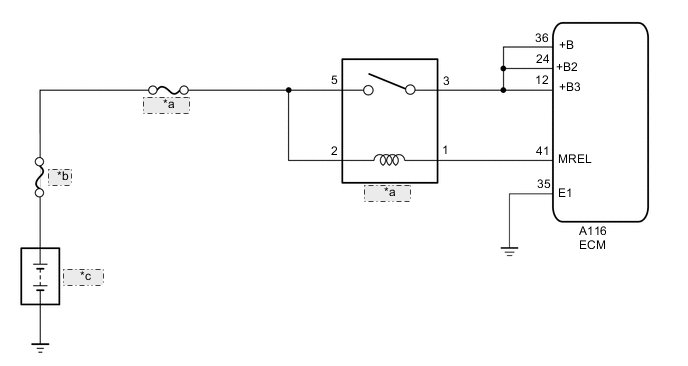
| *a | EFI MAIN |
| *b | MAIN |
| *c | Battery |
CAUTION / NOTICE / HINT
Note
-
Inspect the fuses for circuits related to this system before performing the following inspection procedure.
-
After turning engine switch off, waiting time may be required before disconnecting the cable from the negative (-) battery terminal. Therefore, make sure to read the disconnecting the cable from the negative (-) battery terminal notices before proceeding with work.
Tech Tips
Read freeze frame data using the GTS. The ECM records vehicle and driving condition information as freeze frame data the moment a DTC is stored. When troubleshooting, freeze frame data can help determine if the vehicle was moving or stationary, if the engine was warmed up or not, if the air fuel ratio was lean or rich, and other data from the time the malfunction occurred.
PROCEDURE
-
INSPECT BATTERY
-
Inspect the battery.
OK Battery is not depleted Result Proceed to OK NG
NG 
CHARGE OR REPLACE BATTERY
OK 
-
-
CHECK BATTERY TERMINAL
-
Check that the battery terminals are not loose or corroded.
OK Battery terminals are not loose or corroded Result Proceed to OK NG
NG
REPAIR OR REPLACE BATTERY TERMINAL
OK
-
-
CHECK HARNESS AND CONNECTOR (EFI MAIN RELAY - BATTERY)
-
Disconnect the cable from the negative (-) battery terminal.
-
Disconnect the cable from the positive (+) battery terminal.
-
Remove the EFI MAIN relay from the No. 2 engine room relay block assembly.
-
Measure the resistance according to the value(s) in the table below.
Standard Resistance Tester Connection Condition Specified Condition 5 (EFI MAIN relay holder) - Battery positive (+) terminal Always Below 1 Ω 2 (EFI MAIN relay holder) - Battery positive (+) terminal Always Below 1 Ω 5 (EFI MAIN relay holder) or Battery positive (+) terminal - Body ground other terminals Always 10 kΩ or higher 2 (EFI MAIN relay holder) or Battery positive (+) terminal - Body ground other terminals Always 10 kΩ or higher Result Proceed to OK NG
NG
REPAIR OR REPLACE HARNESS OR CONNECTOR
OK
-
-
CHECK HARNESS AND CONNECTOR (EFI MAIN RELAY- ECM)
-
Remove the EFI MAIN relay from the No. 2 engine room relay block assembly.
-
Disconnect the A116 ECM connector.
-
Measure the resistance according to the value(s) in the table below.
Standard Resistance Tester Connection Condition Specified Condition 3 (EFI MAIN relay holder) - A116-36 (+B) Always Below 1 Ω 3 (EFI MAIN relay holder) - A116-24 (+B2) Always Below 1 Ω 3 (EFI MAIN relay holder) - A116-12 (+B3) Always Below 1 Ω 1 (EFI MAIN relay holder) - A116-41 (MREL) Always Below 1 Ω A116-35 (E1) - Body ground Always Below 1 Ω 3 (EFI MAIN relay holder) or A116-36 (+B) - Body ground and other terminals Always 10 kΩ or higher 3 (EFI MAIN relay holder) or A116-24 (+B2) - Body ground and other terminals Always 10 kΩ or higher 3 (EFI MAIN relay holder) or A116-12 (+B3) - Body ground and other terminals Always 10 kΩ or higher 1 (EFI MAIN relay holder) or A116-41 (MREL) - Body ground and other terminals Always 10 kΩ or higher Result Proceed to OK NG
NG
REPAIR OR REPLACE HARNESS OR CONNECTOR
OK
-
-
CHECK WHETHER DTC OUTPUT RECURS (DTC P0562)
-
Connect the GTS to the DLC3.
-
Turn the engine switch on (IG).
-
Turn the GTS on.
-
Clear the DTCs.
-
Turn the engine switch off and wait for at least 30 seconds.
-
Turn the engine switch on (IG).
-
Turn the GTS on.
-
Wait 5 seconds or more.
-
Enter the following menus: Powertrain / Engine / Trouble Codes.
-
Read the DTCs.
Result Result Proceed to DTC P0562 is output A DTCs are not output B
A
REPLACE ECM Click here
B
CHECK FOR INTERMITTENT PROBLEMS Click here
-