SFI SYSTEM, Diagnostic DTC:P0500
| DTC Code | DTC Name |
|---|---|
| P0500 | Vehicle Speed Sensor "A" |
DESCRIPTION
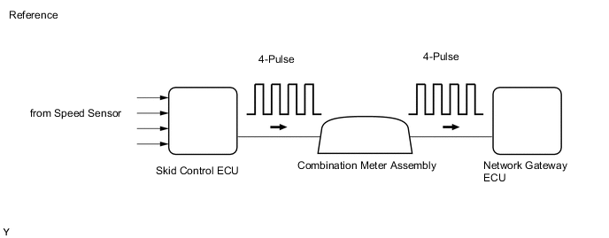
Vehicles, which are equipped with ABS (Anti-lock Brake System), detect the vehicle speed using the skid control ECU (brake actuator assembly) and speed sensor. The speed sensor monitors the wheel rotation speed and sends a signal to the skid control ECU. The skid control ECU converts the wheel speed signal into a 4-pulse signal and transmits it to the network gateway ECU via the combination meter assembly. The network gateway ECU determines the vehicle speed based on the frequency of the pulse signal.
Tech Tips
-
Various systems use the vehicle speed signal distributed from the combination meter assembly. Check all the components possibly related to the speed signal.
-
A voltage of 12 V or 5 V is output from each ECU and then input to the combination meter assembly.
The signal is changed to a pulse signal at the transistor in the combination meter assembly. Each ECU controls its respective system based on this pulse signal.
-
If a short occurs in any of the ECUs or in the wire harness connected to an ECU, all systems using the speed signal will not operate normally.
| DTC No. | Detection Item | DTC Detection Condition | Trouble Area | MIL | Memory |
|---|---|---|---|---|---|
| P0500 | Vehicle Speed Sensor "A" | Enable Criteria
Malfunction Criteria
Diagnostic Mask
Monitor
Potential failure modes
|
|
Comes on | DTC stored |
MONITOR DESCRIPTION
If there is no speed signal from the combination meter assembly even though the network gateway ECU determines that the vehicle is being driven, the network gateway ECU interprets this as a malfunction in the speed signal circuit. The network gateway ECU then illuminates the MIL and stores this DTC.
WIRING DIAGRAM
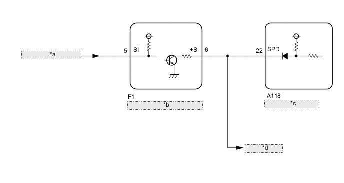
| *a | from Brake Actuator Assembly |
| *b | Combination Meter Assembly |
| *c | Network Gateway ECU |
| *d | to Other ECUs |
CAUTION / NOTICE / HINT
Tech Tips
Read freeze frame data using the GTS. The ECM records vehicle and driving condition information as freeze frame data the moment a DTC is stored. When troubleshooting, freeze frame data can help determine if the vehicle was moving or stationary, if the engine was warmed up or not, if the air fuel ratio was lean or rich, and other data from the time the malfunction occurred.
PROCEDURE
-
READ VALUE USING GTS (VEHICLE SPEED)
-
Connect the GTS to the DLC3.
-
Turn the engine switch on (IG).
-
Turn the GTS on.
-
Enter the following menus: Powertrain / Engine / Data List / Vehicle Speed.
-
Drive the vehicle.
CAUTION:
When performing the confirmation driving pattern, obey all speed limits and traffic laws.
-
Read the value displayed on the GTS.
Result Result Proceed to Values displayed on GTS and speedometer display not equal A Values displayed on GTS and speedometer display equal B
B 
CHECK FOR INTERMITTENT PROBLEMS Click here
A 
-
-
CHECK COMBINATION METER SYSTEM (SPEED SIGNAL CIRCUIT)
-
Check the circuits that send vehicle speed signals to this system in the combination meter system.
Result Proceed to NEXT
NEXT
-
-
CONFIRM WHETHER MALFUNCTION HAS BEEN SUCCESSFULLY REPAIRED
-
Connect the GTS to the DLC3.
-
Turn the engine switch on (IG).
-
Turn the GTS on.
-
Clear the DTCs.
-
Turn the engine switch off and wait for at least 30 seconds.
-
Start the engine.
-
Turn the GTS on.
-
Enter the following menus: Powertrain / Engine / Trouble Codes.
Tech Tips
If no DTCs (no pending DTCs) are output to the GTS, the repair has been successfully completed.
Result Proceed to NEXT
NEXT
END
-