SFI SYSTEM, Diagnostic DTC:P0481
| DTC Code | DTC Name |
|---|---|
| P0481 | Fan2 Circuit Fault |
DESCRIPTION
| DTC No. | Detection Item | DTC Detection Condition | Trouble Area | MIL | Memory |
|---|---|---|---|---|---|
| P0481 | Fan2 Circuit Fault | DTC Detection Condition
Enable Criteria
Malfunction Criteria
Diagnostic Mask
Monitor
Potential failure modes |
|
Comes on | DTC stored |
CAUTION / NOTICE / HINT
Tech Tips
Read freeze frame data using the GTS. The ECM records vehicle and driving condition information as freeze frame data the moment a DTC is stored. When troubleshooting, freeze frame data can help determine if the vehicle was moving or stationary, if the engine was warmed up or not, if the air fuel ratio was lean or rich, and other data from the time the malfunction occurred.
PROCEDURE
-
CHECK TERMINAL VOLTAGE (POWER SOURCE OF COOLING FAN NO.1 RELAY)
-
Disconnect the A116 ECM connector.
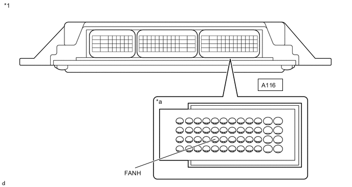
*1 ECM *a Front view of wire harness connector
(to ECM)
-
Turn the engine switch on (IG).
-
Measure the voltage according to the value(s) in the table below.
Standard Voltage Tester Connection Switch Condition Specified Condition A116-29 (FANH) - Body ground Engine switch on (IG) 11 to 14 V Result Result OK NG
OK 
REPLACE ECM Click here
NG 
-
-
INSPECT COOLING FAN NO.2 RELAY
-
Turn the engine switch off.
-
Remove the FAN NO. 2 relay from the No. 1 engine room relay block assembly.
-
Inspect the cooling fan No.2 relay.
Result Result OK NG
NG
REPLACE FAN NO. 2 RELAY
OK
-
-
CHECK HARNESS AND CONNECTOR (ECM - FAN NO. 2 RELAY)
-
Disconnect the A116 ECM connector.
-
Remove the FAN NO. 2 relay from the No. 1 engine room relay block assembly.
-
Measure the resistance according to the value(s) in the table below.
Standard Resistance Tester Connection Condition Specified Condition A116-29 (FANH) - 1 (FAN NO. 2 relay holder) Always Below 1 Ω A116-29 (FANH) or 1 (FAN NO. 2 relay holder) - Body ground and other terminals Always 10 kΩ or higher Result Proceed to OK NG
NG
REPAIR OR REPLACE HARNESS OR CONNECTOR
OK
-
-
CHECK HARNESS AND CONNECTOR (NO. 1 INTEGRATION RELAY - FAN NO. 2)
-
Disconnect the No. 1 integration relay connector.
-
Remove the FAN NO. 2 relay from the No. 1 engine room relay block assembly.
-
Measure the resistance according to the value(s) in the table below.
Standard Resistance Tester Connection Condition Specified Condition 1D-15 - 2 (FAN NO. 2 relay holder) Always Below 1 Ω 1D-15 or 2 (FAN NO. 2 relay holder) - Body ground and other terminals Always 10 kΩ or higher Result Proceed to OK NG
NG
REPAIR OR REPLACE HARNESS OR CONNECTOR
OK
-
-
INSPECT NO. 1 INTEGRATION RELAY
-
Disconnect the No. 1 integration relay connector.
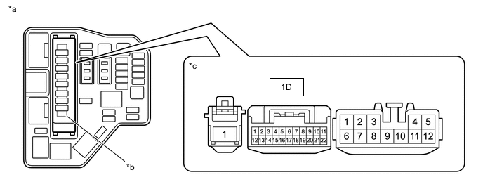
*a Engine Room Relay Block Assembly *b No. 1 Integration Relay *c Front view of wire harness connector
(to No. 1 integration relay)
- - -
Measure the voltage according to the value(s) in the table below.
Standard Voltage Tester Connection Condition Specified Condition 1D-4 - 1D-14 Always Below 1 Ω 1D-4 - 1D-15 Always Below 1 Ω 1D-14 - 1D-15 Always Below 1 Ω Result Proceed to OK NG
NG
REPLACE NO. 1 INTEGRATION RELAY Click here
OK
-
-
CHECK HARNESS AND CONNECTOR (NO. 1 INTEGRATION RELAY - INSTRUMENT PANEL JUNCTION BLOCK ASSEMVBLY)
-
Disconnect the No. 1 integration relay connector.
-
Measure the resistance according to the value(s) in the table below.
Standard Resistance Tester Connection Condition Specified Condition 1D-14 - 3C-27 Always Below 1 Ω Result Proceed to OK NG
NG
REPAIR OR REPLACE HARNESS OR CONNECTOR (NO. 1 INTEGRATION RELAY - BATTERY)
OK
-
-
CHECK TERMINAL VOLTAGE (POWER SOURCE OF INSTRUMENT PANEL JUNCTION BLOCK ASSEMVBLY)
-
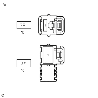
*a Front view of wire harness connector
(to Instrument Panel Junction Block Assembly)
*b for LHD *c for RHD - - Disconnect the Instrument Panel Junction Block Assembly connector.
-
Measure the voltage according to the value(s) in the table below.
Standard Voltage for LHD Tester Connection Condition Specified Condition 3E-1 - Body ground Always 11 to 14 V for RHD Tester Connection Condition Specified Condition 3F-1 - Body ground Always 11 to 14 V Result Result OK NG
NG
REPAIR OR REPLACE HARNESS OR CONNECTOR
OK
-
-
CHECK HARNESS AND CONNECTOR (INSTRUMENT PANEL JUNCTION BLOCK ASSEMVBLY - BODY GROUND)
-
Disconnect the 3B Instrument Panel Junction Block Assembly connector.
-
Measure the resistance according to the value(s) in the table below.
Standard Resistance Tester Connection Condition Specified Condition 3B-8 - Body ground Always Below 1 Ω Result Proceed to OK NG
OK
CHECK FOR INTERMITTENT PROBLEMS Click here
NG
REPAIR OR REPLACE HARNESS OR CONNECTOR
-