SFI SYSTEM, Diagnostic DTC:P0140
| DTC Code | DTC Name |
|---|---|
| P0140 | O2 Sensor Circuit No Activity Detected Bank 1 Sensor 2 |
DESCRIPTION
| DTC No. | Detection Item | DTC Detection Condition | Trouble Area | MIL | Memory |
|---|---|---|---|---|---|
| P0140 | O2 Sensor Circuit No Activity Detected Bank 1 Sensor 2 | DTC Detection Condition
Enable Criteria
Malfunction Criteria
Diagnostic Mask
Monitor
Potential failure modes |
|
Comes on | DTC stored |
MONITOR DESCRIPTION
The oxygen sensor is electrically heated to improve response from start.
The sensor consists of zirconia electrode between two platinum plates. When zirconia comes into contact with oxygen, it becomes an electrical conductor. The exhaust gases passes through louvers in the sensor. One plate is in contact with the outside air and the other plate is in contact with the exhaust gases. The platinum plate in contact with the air is electrically negative due to the oxygen in the atmosphere and the plate in contact with the exhaust gases is electrically positive. This will cause a difference in electrical potential to develop between the two plates. Thus the voltage across the platinum plates ranges approximately from 100 millivolts to 900 millivolts, depending on the oxygen content of the exhaust gases. Thus when the air/fuel mixture is rich, the oxygen sensor output will be high. If the air/fuel mixture is lean, the oxygen sensor output will be low. The post catalyst oxygen sensor performance is a good indicator of catalyst efficiency.
CAUTION / NOTICE / HINT
Tech Tips
-
The internal resistance of the heated oxygen sensor (sensor 2) cannot be measured using a tester.
-
Sensor 1 refers to the sensor closest to the engine assembly.
-
Sensor 2 refers to the sensor farthest away from the engine assembly.
-
Read freeze frame data using the GTS. Freeze frame data records the engine condition when malfunctions are detected. When troubleshooting, freeze frame data can help determine if the vehicle was moving or stationary, if the engine was warmed up or not, if the air fuel ratio was lean or rich, and other data from the time the malfunction occurred.
PROCEDURE
-
INSPECT HEATED OXYGEN SENSOR (SENSOR 2) (HEATER RESISTANCE)
-
Inspect the heated oxygen sensor (sensor 2).
Result Proceed to OK NG
NG 
REPLACE HEATED OXYGEN SENSOR (SENSOR 2) Click here
OK 
-
-
CHECK TERMINAL VOLTAGE (POWER SOURCE OF HEATED OXYGEN SENSOR (SENSOR 2))
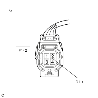
*a Front view of wire harness connector
(to Heated Oxygen Sensor (Sensor 2))
-
Disconnect the heated oxygen sensor (sensor 2) connector.
-
Turn the engine switch on (IG).
-
Measure the voltage according to the value(s) in the table below.
Standard Voltage Tester Connection Condition Specified Condition F142-2 (DIL+) - Body ground Engine switch on (IG) 11 to 14 V Result Proceed to OK NG
NG 
INSPECT EFI MAIN RELAY Click here
OK
-
-
CHECK HARNESS AND CONNECTOR (HEATED OXYGEN SENSOR (SENSOR 2) - ECM)
-
Disconnect the F142 heated oxygen sensor (sensor 2) connector.
-
Disconnect the B142 ECM connector.
-
Measure the resistance according to the value(s) in the table below.
Standard Resistance Tester Connection Condition Specified Condition F142-1 (HT1B) - B142-46 (HT1B) Always Below 1 Ω F142-1 (HT1B) or B142-46 (HT1B) - Body ground and other terminals Always 10 kΩ or higher Result Proceed to OK NG
NG
REPAIR OR REPLACE HARNESS OR CONNECTOR
OK
-
-
CHECK WHETHER DTC OUTPUT RECURS (DTC P0140)
-
Connect the GTS to the DLC3.
-
Turn the engine switch on (IG).
-
Turn the GTS on.
-
Clear the DTCs.
-
Turn the engine switch off and wait for at least 30 seconds.
-
Start the engine.
-
Allow the engine to idle for 20 minutes or more.
-
Turn the GTS on.
-
Enter the following menus: Powertrain / Engine / Trouble Codes.
-
Read the DTCs.
Result Result Proceed to DTCs are not output A DTC P0140 is output B
A
CHECK FOR INTERMITTENT PROBLEMS Click here
B
REPLACE ECM Click here
-
-
INSPECT EFI MAIN RELAY
-
Inspect the EFI MAIN relay.
Result Proceed to OK NG
NG
REPLACE EFI MAIN RELAY
OK
-
-
CHECK HARNESS AND CONNECTOR (EFI MAIN RELAY - HEATED OXYGEN SENSOR (SENSOR 1))
-
Remove the EFI MAIN relay from the No. 2 engine room relay block assembly.
-
Disconnect the F142 heated oxygen sensor (sensor 2) connector.
-
Measure the resistance according to the value(s) in the table below.
Standard Resistance Tester Connection Condition Specified Condition F142-2 (DIL+) - 3 (EFI MAIN relay holder) Always Below 1 Ω F142-2 (DIL+) or 3 (EFI MAIN relay holder) - Body ground and other terminals Always 10 kΩ or higher Result Proceed to OK NG
OK
CHECK ECM POWER SOURCE CIRCUIT Click here
NG
REPAIR OR REPLACE HARNESS OR CONNECTOR
-