SFI SYSTEM, Diagnostic DTC:P0133
| DTC Code | DTC Name |
|---|---|
| P0133 | O2 Sensor Circuit Slow Response Bank 1 Sensor 1 |
DESCRIPTION
| DTC No. | Detection Item | DTC Detection Condition | Trouble Area | MIL | Memory |
|---|---|---|---|---|---|
| P0133 | O2 Sensor Circuit Slow Response Bank 1 Sensor 1 | DTC Detection Condition
Enable Criteria
Malfunction Criteria (1)
Malfunction Criteria (2)
Malfunction Criteria (3)
Malfunction Criteria (4)
Diagnostic Mask
Monitor
Potential failure modes |
|
Comes on | DTC stored |
Tech Tips
Rich-Lean cycle
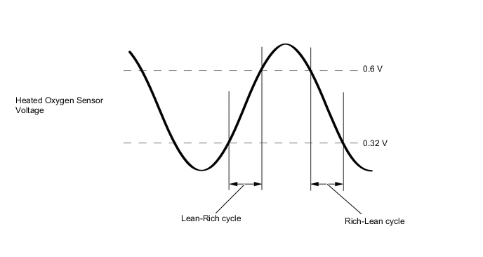
MONITOR DESCRIPTION
The oxygen sensor is electrically heated to improve response after start.
The sensor consists of a zirconia electrode between two platinum plates. When zirconia comes into contact with oxygen, it becomes an electrical conductor. The exhaust gases pass through louvers in the sensor. One plate is in contact with the outside air and the other plate is in contact with the exhaust gases. The platinum plate in contact with the air is electrically negative due to the oxygen in the atmosphere and the plate in contact with the exhaust gases is electrically positive. This will cause a difference in electrical potential to develop between the two plates. Thus the voltage across the platinum plates ranges approximately from 100 millivolts to 900 millivolts, depending on the oxygen content of the exhaust gases. Thus when the air/fuel mixture is rich, the oxygen sensor output will be high. If the air/fuel mixture is lean, the oxygen sensor output will be low.
CAUTION / NOTICE / HINT
Tech Tips
-
A high heated oxygen sensor voltage (0.55 V or more) in most time could be caused by a rich air fuel mixture. Check for conditions that would cause the engine to run rich.
-
A low heated oxygen sensor voltage (0.4 V or less) in most time could be caused by a lean air fuel mixture. Check for conditions that would cause the engine to run lean.
-
Sensor 1 refers to the sensor closest to the engine assembly.
-
Sensor 2 refers to the sensor farthest away from the engine assembly.
-
Read freeze frame data using the GTS. Freeze frame data records the engine condition when malfunctions are detected. When troubleshooting, freeze frame data can help determine if the vehicle was moving or stationary, if the engine was warmed up or not, if the air fuel ratio was lean or rich, and other data from the time the malfunction occurred.
PROCEDURE
-
CHECK ANY OTHER DTC OUTPUT (IN ADDITION TO DTC P0133)
-
Connect the GTS to the DLC3.
-
Turn the engine switch on (IG).
-
Turn the GTS on.
-
Enter the following menus: Powertrain / Engine / Trouble Codes.
-
Read the DTCs.
Result Result Proceed to DTC P0133 is output A DTC P0133 and other DTCs are output B Tech Tips
If any DTCs other than P0133 are output, troubleshoot those DTCs first.
B 
GO TO DTC CHART Click here
A 
-
-
CHECK HARNESS AND CONNECTOR (HEATED OXYGEN SENSOR (SENSOR 1) - ECM)
-
Disconnect the B37 heated oxygen sensor (sensor 1) connector.
-
Disconnect the B142 ECM connector.
-
Measure the resistance according to the value(s) in the table below.
Standard Resistance Tester Connection Condition Specified Condition B37-3 (A1A+) - B142-19 (A1A+) Always Below 1 Ω B37-1 (HA1A) - B142-20 (HA1A) Always Below 1 Ω B37-4 (A1A-) - B142-33 (A1A-) Always Below 1 Ω B37-3 (A1A+) or B142-19 (A1A+) - Body ground and other terminals Always 10 kΩ or higher B37-1 (HA1A) or B142-20 (HA1A) - Body ground and other terminals Always 10 kΩ or higher Result Proceed to OK NG
NG
REPAIR OR REPLACE HARNESS OR CONNECTOR
OK
-
-
REPLACE HEATED OXYGEN SENSOR (SENSOR 1)
-
Replace the heated oxygen sensor (sensor 1).
Result Proceed to NEXT
NEXT
-
-
CHECK WHETHER DTC OUTPUT RECURS (DTC P0133)
-
Connect the GTS to the DLC3.
-
Turn the engine switch on (IG).
-
Turn the GTS on.
-
Clear the DTCs.
-
Turn the engine switch off and wait for at least 30 seconds.
-
Start the engine and warm it up.
-
Using the GTS, confirm the vehicle conditions recorded in the freeze frame data which were present when the DTC was stored.
-
Turn the GTS on.
-
Enter the following menus: Powertrain / Engine / Trouble Codes.
-
Read the DTCs.
Result Result Proceed to DTCs are not output A DTC P0133 is output B
A
END
B
-
-
CHECK WHETHER MISFIRE OCCURS
-
Check the idling condition.
OK Rough idling does not occur. Result Proceed to OK NG
NG
TROUBLESHOOT MISFIRE Click here
OK
-
-
CHECK FUEL PRESSURE
-
Check the fuel pressure.
Result Proceed to OK NG
NG
REPAIR OR REPLACE FUEL SYSTEM
OK
-
-
INSPECT FUEL INJECTOR ASSEMBLY (INJECTION AND VOLUME)
-
Check the injector volume.
Result Proceed to OK NG
OK
CHECK FOR EXHAUST GAS LEAK
NG
REPLACE FUEL INJECTOR ASSEMBLY Click here
-