SFI SYSTEM, Diagnostic DTC:P0102
| DTC Code | DTC Name |
|---|---|
| P0102 | Mass or Volume Air Flow Sensor "A" Circuit Low |
DESCRIPTION
| DTC No. | Detection Item | DTC Detection Condition | Trouble Area | MIL | Memory |
|---|---|---|---|---|---|
| P0102 | Mass or Volume Air Flow Sensor "A" Circuit Low | Enable Criteria
Malfunction Criteria
Diagnostic Mask
Monitor
Potential failure modes
|
|
Comes on | DTC stored |
MONITOR DESCRIPTION
The Mass Air Flow (MAF) sensor is incorporated into the air box, and measures both intake air flow rate and Intake Air Temperature (IAT). The MAF sensor uses a hot wire exposed to the airflow, which is maintained at a constant temperature by a constant current flow. This is achieved within the sensor unit by varying the voltage applied to the hot wire. This voltage is the output signal from the MAF sensor.
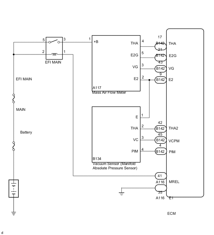
WIRING DIAGRAM
CAUTION / NOTICE / HINT
Note
Inspect the fuses for circuits related to this system before performing the following procedure.
Tech Tips
Read freeze frame data using the GTS. The ECM records vehicle and driving condition information as freeze frame data the moment a DTC is stored. When troubleshooting, freeze frame data can help determine if the vehicle was moving or stationary, if the engine was warmed up or not, if the air fuel ratio was lean or rich, and other data from the time the malfunction occurred.
PROCEDURE
-
READ OUTPUT DTC (DTC P0102)
-
Connect the GTS to the DLC3.
-
Turn the engine switch on (IG).
-
Turn the GTS on.
-
Enter the following menus: Powertrain / Engine / Trouble Codes.
-
Read the DTCs.
Result Result Proceed to DTC P0102 is output A DTC P0102 and other DTCs are output B
B 
GO TO DTC CHART Click here
A 
-
-
CHECK TERMINAL VOLTAGE (POWER SOURCE OF MASS AIR FLOW METER)
-
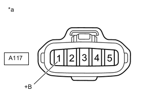
*a Front view of wire harness connector
(to Mass Air Flow Meter)
Disconnect the mass air flow meter connector.
-
Turn the engine switch on (IG).
-
Measure the voltage according to the value(s) in the table below.
Standard Voltage Tester Connection Switch Condition Specified Condition A117-1 (+B) - Body ground Engine switch on (IG) 11 to 14 V Result Proceed to OK NG
NG 
INSPECT EFI MAIN RELAY Click here
OK
-
-
CHECK HARNESS AND CONNECTOR (MASS AIR FLOW METER - ECM)
-
Disconnect the A117 mass air flow meter connector.
-
Disconnect the B142 ECM connector.
-
Measure the resistance according to the value(s) in the table below.
Standard Resistance Tester Connection Condition Specified Condition A117-3 (VG) - B142-43 (VG) Always Below 1 Ω A117-5 (E2G) - 142-21 (E2G) Always Below 1 Ω A117-3 (VG) or B142-43 (VG) - Body ground Always 10 kΩ or higher Result Proceed to OK NG
NG
REPAIR OR REPLACE HARNESS OR CONNECTOR
OK
-
-
INSPECT MASS AIR FLOW METER
-
Inspect the mass air flow meter, referring to the On-vehicle Inspection for mass air flow meter.
-
Inspect the mass air flow meter, referring to the Inspection for mass air flow meter.
-
Inspect the function of the mass air flow meter.
-
Connect the GTS to the DLC3.
-
Turn the engine switch on (IG).
-
Turn the GTS on.
-
Enter the following menus: Powertrain / Engine / Data List / Primary / MAF.
-
Start the engine.
-
Check that the MAF value changes when the engine is raced.
OK The reading changes.
Result Proceed to OK NG -
OK
REPLACE ECM Click here
NG
REPLACE MASS AIR FLOW METER Click here
-
-
INSPECT EFI MAIN RELAY
-
Inspect the EFI MAIN relay.
Result Proceed to OK NG
NG
REPLACE EFI MAIN RELAY
OK
-
-
CHECK HARNESS AND CONNECTOR (EFI MAIN RELAY - MASS AIR FLOW METER)
-
Remove the EFI MAIN relay from the No. 2 engine room relay block assembly.
-
Disconnect the A117 mass air flow meter connector.
-
Measure the resistance according to the value(s) in the table below.
Standard Resistance Tester Connection Condition Specified Condition 3 (EFI MAIN relay holder) - A117-1 (+B) Always Below 1 Ω 3 (EFI MAIN relay holder) or A117-1 (+B) - Body ground and other terminals Always 10 kΩ or higher Result Proceed to OK NG
OK
CHECK ECM POWER SOURCE CIRCUIT Click here
NG
REPAIR OR REPLACE HARNESS OR CONNECTOR
-