SFI SYSTEM, Diagnostic DTC:P0097
| DTC Code | DTC Name |
|---|---|
| P0097 | Intake Air Temperature Sensor 2 Circuit Low Bank 1 |
DESCRIPTION
| DTC No. | Detection Item | DTC Detection Condition | Trouble Area | MIL | Memory |
|---|---|---|---|---|---|
| P0097 | Intake Air Temperature Sensor 2 Circuit Low Bank 1 | Enable Criteria
Malfunction Criteria
Diagnostic Mask
Monitor
Potential failure modes
|
|
Comes on | DTC stored |
MONITOR DESCRIPTION
These DTCs are stored when a malfunction is detected in the intake air temperature sensor circuit. If the difference between the intake air temperature and the ambient temperature is outside of the threshold when the turn the engine switch on (IG) after a few hours have elapsed since the engine was stopped, or there is an open or short in the intake air temperature sensor circuit, the ECM will store a DTC.
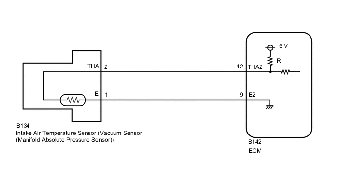
WIRING DIAGRAM
CAUTION / NOTICE / HINT
Tech Tips
Read freeze frame data using the GTS. The ECM records vehicle and driving condition information as freeze frame data the moment a DTC is stored. When troubleshooting, freeze frame data can help determine if the vehicle was moving or stationary, if the engine was warmed up or not, if the air fuel ratio was lean or rich, and other data from the time the malfunction occurred.
PROCEDURE
-
READ VALUE USING GTS (INTAKE AIR)
-
Connect the GTS to the DLC3.
-
Turn the engine switch on (IG).
-
Turn the GTS on.
-
Enter the following menus: Powertrain / Engine / Data List / Intake Air.
-
Read the value displayed on the GTS.
OK Same as actual intake air temperature. Result Result Proceed to -40°C (-40°F) A Same as actual intake air temperature B Tech Tips
-
If there is an open circuit, the GTS indicates -40°C (-40°F).
-
If there is a short circuit, the GTS indicates 140°C (284°F).
-
B 
CHECK FOR INTERMITTENT PROBLEMS Click here
A 
-
-
READ VALUE USING GTS (CHECK FOR OPEN IN WIRE HARNESS)
-
Disconnect the vacuum sensor (manifold absolute pressure sensor) connector.
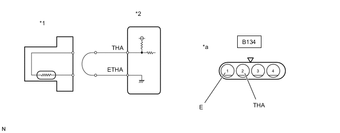
*1 Vacuum sensor (manifold absolute pressure sensor) *2 ECM *a Front view of wire harness connector
(to Vacuum sensor (manifold absolute pressure sensor))
- - -
Connect terminals 2 (THA) and 1 (E) of the vacuum sensor (manifold absolute pressure sensor) connector on the wire harness side.
-
Connect the GTS to the DLC3.
-
Turn the engine switch on (IG).
-
Turn the GTS on.
-
Enter the following menus: Powertrain / Engine / Data List / Intake Air.
-
Read the value displayed on the GTS.
Standard Value 140°C (284°F) Tech Tips
Perform "Inspection After Repair" after replacing the vacuum sensor (manifold absolute pressure sensor).
Result Proceed to OK NG
OK
REPLACE VACUUM SENSOR (MANIFOLD ABSOLUTE PRESSURE SENSOR) Click here
NG
-
-
CHECK HARNESS AND CONNECTOR (ECM - VACUUM SENSOR (MANIFOLD ABSOLUTE PRESSURE SENSOR))
-
Disconnect the B142 ECM connector.
-
Disconnect the B134 vacuum sensor (manifold absolute pressure sensor) connector.
-
Measure the resistance according to the value(s) in the table below.
Standard Resistance Tester Connection Condition Specified Condition B142-42 (THA2) - B134-2 (THA) Always Below 1 Ω B142-9 (E2) - B134-1 (E) Always Below 1 Ω Result Proceed to OK NG
OK
REPLACE ECM Click here
NG
REPAIR OR REPLACE HARNESS OR CONNECTOR
-