SFI SYSTEM, Diagnostic DTC:P0076
| DTC Code | DTC Name |
|---|---|
| P0076 | Intake Valve Control Solenoid Circuit Low Bank 1 |
DESCRIPTION
| DTC No. | Detection Item | DTC Detection Condition | Trouble Area | MIL | Memory |
|---|---|---|---|---|---|
| P0076 | Intake Valve Control Solenoid Circuit Low Bank 1 | Enable Criteria
Malfunction Criteria
Diagnostic Mask
Monitor
Potential failure modes
|
|
Comes on | DTC stored |
MONITOR DESCRIPTION
This DTC is designed to detect an open or short in the camshaft timing oil control valve assembly (for intake camshaft) circuit. If the camshaft timing oil control valve assembly duty-cycle is excessively high or low while the engine switch is on (IG) or the engine is running, the ECM will illuminate the MIL and store this DTC.
WIRING DIAGRAM
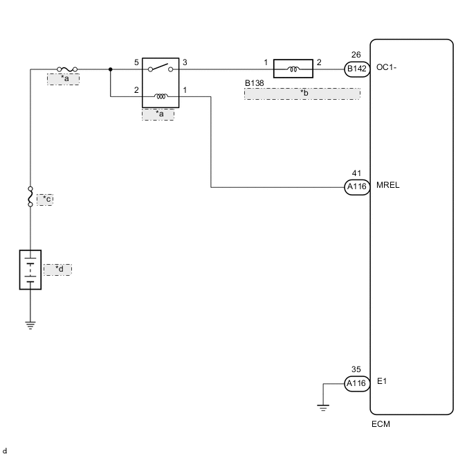
| *a | EFI MAIN |
| *b | Camshaft Timing Oil Control Valve Assembly (for Intake Camshaft) |
| *c | MAIN |
| *d | Battery |
CAUTION / NOTICE / HINT
Tech Tips
Read freeze frame data using the GTS. The ECM records vehicle and driving condition information as freeze frame data the moment a DTC is stored. When troubleshooting, freeze frame data can help determine if the vehicle was moving or stationary, if the engine was warmed up or not, if the air fuel ratio was lean or rich, and other data from the time the malfunction occurred.
PROCEDURE
-
READ OUTPUT DTC (DTC P0076)
-
Connect the GTS to the DLC3.
-
Turn the engine switch on (IG).
-
Turn the GTS on.
-
Clear the DTC after recording the freeze frame data and DTC.
-
Turn the engine switch off and wait for at least 30 seconds.
-
Turn the engine switch on (IG) and wait 5 seconds.
-
Turn the GTS on.
-
Enter the following menus: Powertrain / Engine / Trouble Codes.
-
Read the DTCs.
Result Result Proceed to DTC P0076 is output A DTCs are not output B
B 
CHECK FOR INTERMITTENT PROBLEMS Click here
A 
-
-
CHECK TERMINAL VOLTAGE (POWER SOURCE OF CAMSHAFT OIL CONTROL VALVE ASSEMBLY (FOR INTAKE CAMSHAFT))
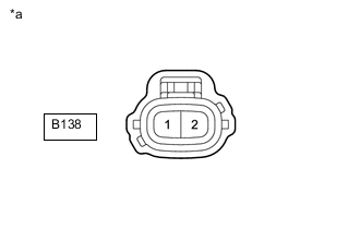
*a Front view of wire harness connector
(to Camshaft Timing Oil Control Valve Assembly (for Intake Camshaft))
-
Disconnect the camshaft timing oil control valve assembly (for intake camshaft) connector.
-
Turn the engine switch on (IG).
-
Measure the voltage according to the value(s) in the table below.
Standard Voltage Tester Connection Switch Condition Specified Condition B138-1 - Body ground Engine switch on (IG) 11 to 14 V Result Proceed to OK NG
NG 
INSPECT EFI MAIN RELAY Click here
OK
-
-
INSPECT CAMSHAFT TIMING OIL CONTROL VALVE ASSEMBLY (FOR INTAKE CAMSHAFT)
-
Inspect the camshaft timing oil control valve assembly (for intake camshaft).
Result Proceed to OK NG
NG
REPLACE CAMSHAFT TIMING OIL CONTROL VALVE ASSEMBLY (FOR INTAKE CAMSHAFT) Click here
OK
-
-
CHECK HARNESS AND CONNECTOR (CAMSHAFT TIMING OIL CONTROL VALVE ASSEMBLY (FOR INTAKE CAMSHAFT) - ECM)
-
Disconnect the B138 camshaft timing oil control valve assembly (for intake camshaft) connector.
-
Disconnect the B142 ECM connector.
-
Measure the resistance according to the value(s) in the table below.
Standard Resistance Tester Connection Condition Specified Condition B138-2 - B142-26 (OC1-) Always Below 1 Ω B138-2 or B142-26 (OC1-) - Body ground and other terminals Always 10 kΩ or higher Result Proceed to OK NG
OK
REPLACE ECM Click here
NG
REPAIR OR REPLACE HARNESS OR CONNECTOR
-
-
INSPECT EFI MAIN RELAY
-
Inspect the EFI MAIN relay.
Result Proceed to OK NG
NG
REPLACE EFI MAIN RELAY
OK
-
-
CHECK HARNESS AND CONNECTOR (EFI MAIN RELAY - CAMSHAFT TIMING OIL CONTROL VALVE ASSEMBLY (FOR INTAKE CAMSHAFT))
-
Remove the EFI MAIN relay from the No. 2 engine room relay block assembly.
-
Disconnect the B138 camshaft timing oil control valve assembly (for intake camshaft) connector.
-
Measure the resistance according to the value(s) in the table below.
Standard Resistance Tester Connection Condition Specified Condition 3 (EFI MAIN relay holder) - B138-1 Always Below 1 Ω 3 (EFI MAIN relay holder) or B138-1 - Body ground and other terminals Always 10 kΩ or higher Result Proceed to OK NG
OK
CHECK ECM POWER SOURCE CIRCUIT Click here
NG
REPAIR OR REPLACE HARNESS OR CONNECTOR
-