INTEGRATION RELAY INSPECTION
CAUTION / NOTICE / HINT
Note
Inspect the fuses for circuits related to the No. 1 integration relay before performing the following inspection procedure.
PROCEDURE
-
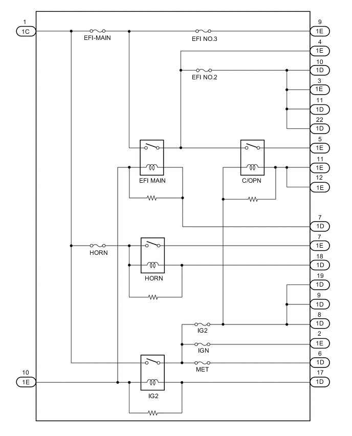
INSPECT NO. 1 INTEGRATION RELAY
-
Inspect the EFI MAIN relay resistance.
-
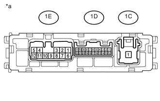
*a Component without harness connected
(No. 1 Integration Relay)
Measure the resistance according to the value(s) in the table below.
Standard Resistance Tester Connection Condition Specified Condition 1C-1 - 1D-10
1C-1 - 1D-11
1C-1 - 1D-12
1C-1 - 1E-3
1C-1 - 1E-4
1C-1 - 1E-5
Battery voltage not applied between
1E-10 - 1D-7 terminals
10 kΩ or higher Battery positive (+) → 1E - 10
Battery negative (-) → 1D - 7
Below 1 Ω If the result is not as specified, replace the No. 1 integration relay.
-
-
Inspect the IG2 relay resistance.
-
*a Component without harness connected
(No. 1 Integration Relay)
Measure the resistance according to the value(s) in the table below.
Standard Resistance Tester Connection Condition Specified Condition 1C-1 - 1D-6
1C-1 - 1D-8
1C-1 - 1D-9
1C-1 - 1D-19
1C-1 - 1E-2
1C-1 - 1E-11
1C-1 - 1E-12
Battery voltage not applied between
1E-10 - 1D-17 terminals
10 kΩ or higher Battery positive (+) → 1E - 10
Battery negative (-) → 1D - 7
Below 1 Ω If the result is not as specified, replace the No. 1 integration relay.
-
-
Inspect the HORN relay resistance.
-
*a Component without harness connected
(No. 1 Integration Relay)
Measure the resistance according to the value(s) in the table below.
Standard Resistance Tester Connection Condition Specified Condition 1C-1 - 1E-7 Battery voltage not applied between
1C-1 - 1D-18 terminals
10 kΩ or higher Battery positive (+) → 1E - 10
Battery negative (-) → 1D - 18
Below 1 Ω If the result is not as specified, replace the No. 1 integration relay.
-
-
C/OPEN RELAY
-
*a Component without harness connected
(No. 1 Integration Relay)
Measure the resistance according to the value(s) in the table below.
Standard Resistance Tester Connection Condition Specified Condition 1E-5 - 1D-10
1E-5 - 1D-11
1E-5 - 1D-22
1E-5 - 1E-3
1E-5 - 1E-4
Battery voltage not applied between terminals 1E - 11 and 1D - 8 10 kΩ or higher Battery voltage not applied between terminals 1E - 11 and 1D - 9 Battery voltage not applied between terminals 1E - 11 and 1D - 19 Battery voltage not applied between terminals 1E - 12 and 1D - 8 Battery voltage not applied between terminals 1E - 12 and 1D - 9 Battery voltage not applied between terminals 1E - 12 and 1D - 19 Battery positive (+) → 1E - 11
Battery negative (-) → 1D - 8
Below 1 Ω Battery positive (+) → 1E - 11
Battery negative (-) → 1D - 9
Battery positive (+) → 1E - 11
Battery negative (-) → 1D - 19
Battery positive (+) → 1E - 12
Battery negative (-) → 1D - 8
Battery positive (+) → 1E - 12
Battery negative (-) → 1D - 9
Battery positive (+) → 1E - 12
Battery negative (-) → 1D - 19
If the result is not as specified, replace the No. 1 integration relay.
-
-