SFI SYSTEM, Diagnostic DTC:P0420
| DTC Code | DTC Name |
|---|---|
| P0420 | Catalyst System Efficiency Below Threshold Bank 1 |
MONITOR DESCRIPTION
The ECU compares the waveform of the oxygen sensors located before and after the catalyst to determine whether or not the catalyst has deteriorated. If the catalyst is functioning normally, the front oxygen sensor will be switching between rich and lean while the rear oxygen sensor should also be switching between rich and lean, but more slowly. When both the oxygen sensor waveforms change at a similar rate, it indicates that the catalyst performance has deteriorated. The ECU counts the number of pre and post catalyst oxygen sensor switches and divides one by the other to determine a ratio. If this ratio is too high a fault will be indicated.
| DTC No. | Detection Item | DTC Detection Condition | Trouble Area | MIL | Memory |
|---|---|---|---|---|---|
| P0420 | Catalyst System Efficiency Below Threshold Bank 1 | DTC Detection Condition
Enable Criteria
Malfunction Criteria
Diagnostic Mask
Monitor
Potential failure modes |
|
Comes on | DTC stored |
CATALYST LOCATION
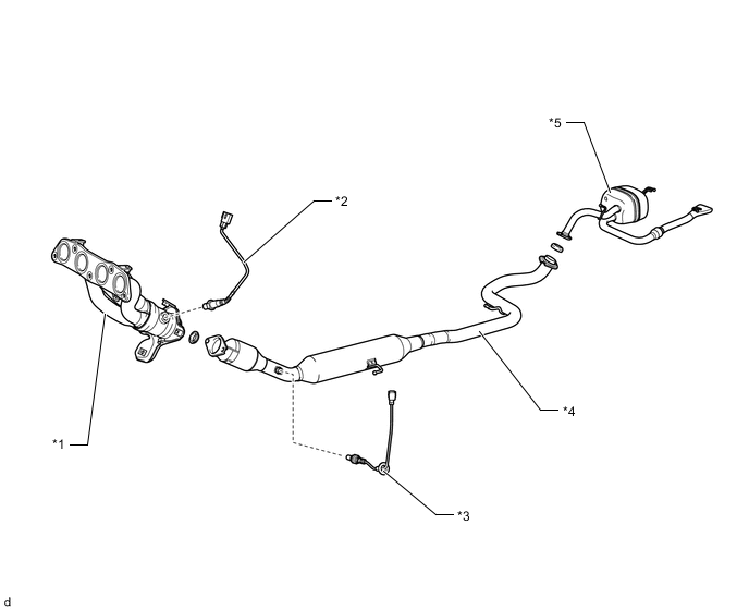
| *1 | Exhaust Manifold | *2 | Heated Oxygen Sensor (Sensor 1) |
| *3 | Heated Oxygen Sensor (Sensor 2) | *4 | Front Exhaust Pipe Assembly (TWC: Front Catalyst) |
| *5 | Tail Exhaust Pipe Assembly | - | - |
Note
Replace the front exhaust pipe assembly (*4) when catalyst replacement is necessary. (Excluding heated oxygen sensor (sensor 1)*2 and heated oxygen sensor (sensor 2)*3)
CAUTION / NOTICE / HINT
Tech Tips
-
If a malfunction cannot be found when troubleshooting DTC P0420, a lean or rich abnormality may be the cause. Perform troubleshooting by following the inspection procedure for P0171 (System Too Lean), and P0172 (System Too Rich).
-
Read freeze frame data using the GTS. The ECM records vehicle and driving condition information as freeze frame data the moment a DTC is stored. When troubleshooting, freeze frame data can help determine if the vehicle was moving or stationary, if the engine was warmed up or not, if the air fuel ratio was lean or rich, and other data from the time the malfunction occurred.
PROCEDURE
-
CHECK ANY OTHER DTCS OUTPUT (IN ADDITION TO DTC P0420)
-
Connect the GTS to the DLC3.
-
Turn the engine switch on (IG).
-
Turn the GTS on.
-
Enter the following menus: Powertrain / Engine / Trouble Codes.
-
Read the DTCs.
Result Result Proceed to DTC P0420 is output A DTC P0420 and other DTCs are output B Tech Tips
If any DTCs other than P0420 are output, troubleshoot those DTCs first.
B 
GO TO DTC CHART Click here
A 
-
-
READ VALUE USING GTS (O2S B1S1 AND O2S B1S2)
-
Connect the GTS to the DLC3.
-
Start the engine and warm it up.
-
Turn the GTS on.
-
Warm up the engine and run the engine at an engine speed of 2500 rpm for approximately 90 seconds.
-
Enter the following menus: Powertrain / Engine / Data List / O2S B1S1 and O2S B1S2.
-
Allow the engine to idle.
-
Monitor the voltage outputs of the heated oxygen sensor (sensor 1) and heated oxygen sensor (sensor 2) (O2S B1S1 and O2S B1S2) displayed on the GTS.
Note
-
The heated oxygen sensor (sensor 1) has an output delay of a few seconds and the heated oxygen sensor (sensor 2) has a maximum output delay of approximately 20 seconds.
-
Read the output voltage immediately after warming up the heated oxygen sensor (sensor 1) and heated oxygen sensor (sensor 2) to avoid an inaccurate reading due to a sensor cooling.
Standard GTS Display
(Sensor)
Status Voltage O2S B1S1
(Heated oxygen sensor (sensor 1))
Rich Higher than 0.6 V Lean Below 0.322 V O2S B1S2
(Heated oxygen sensor (sensor 2))
Rich Higher than 0.6 V Lean Below 0.3 V Result Status O2S B1S1 Status O2S B1S2 Actual air fuel ratio, heated oxygen sensor (sensor 1) and heated oxygen sensor (sensor 2) condition Misfire Main Suspected Trouble Area Proceed to Lean/Rich Lean/Rich Normal -
-
Three-way catalytic converter
-
Gas leak from exhaust system
A Lean/Rich Lean Heated oxygen sensor malfunction -
-
Heated oxygen sensor (sensor 2)
-
Gas leak from exhaust system
-
Three-way catalytic converter
B Lean/Rich Rich Heated oxygen sensor malfunction -
-
Heated oxygen sensor (sensor 2)
-
Gas leak from exhaust system
-
Three-way catalytic converter
Lean Lean Actual air fuel ratio lean May occur
-
Extremely lean actual air fuel ratio
-
Gas leak from exhaust system
C Rich Rich Actual air fuel ratio rich -
-
Extremely rich actual air fuel ratio
-
Gas leak from exhaust system
Tech Tips
-
Lean: Heated oxygen sensor (sensor 1) or Heated oxygen sensor (sensor 2) (O2S B1S1 and O2S B1S2) output voltage is consistently below 0.3 V.
-
Rich: Heated oxygen sensor (sensor 1) or Heated oxygen sensor (sensor 2) (O2S B1S1 and O2S B1S2) output voltage is consistently below 0.6 V.
-
Lean/Rich: Heated oxygen sensors alternate correctly.
-
B 
CHECK FOR EXHAUST GAS LEAK Click here
C
CHECK FOR EXHAUST GAS LEAK Click here
A
-
-
CHECK FOR EXHAUST GAS LEAK
-
Check for exhaust gas leaks.
OK No gas leaks. Result Proceed to OK NG
NG
GO TO STEP 9 Click here
OK
-
-
REPLACE FRONT EXHAUST PIPE ASSEMBLY (TWC: FRONT CATALYST)
Note
Replace the front exhaust pipe assembly (TWC: Front catalyst) when catalyst replacement is necessary.
Tech Tips
Confirm the replacement parts, referring to the illustration in the Catalyst Location.
-
Replace the front exhaust pipe assembly (TWC: Front catalyst).
Result Proceed to NEXT
NEXT
END
-
-
CHECK FOR EXHAUST GAS LEAK
-
Check for exhaust gas leaks.
OK No gas leaks. Result Proceed to OK NG
NG
GO TO STEP 9 Click here
OK
-
-
REPLACE HEATED OXYGEN SENSOR (SENSOR 2)
-
Replace the heated oxygen sensor (sensor 2).
Result Proceed to NEXT
NEXT
GO TO STEP 10 Click here
-
-
CHECK FOR EXHAUST GAS LEAK
-
Check for exhaust gas leaks.
OK No gas leaks. Result Proceed to OK NG
NG
REPAIR OR REPLACE EXHAUST GAS LEAK POINT Click here
OK
-
-
CHECK CAUSE OF EXTREMELY RICH OR LEAN ACTUAL AIR FUEL RATIO
-
Check the cause of extremely rich or lean actual air fuel ratio, referring to the DTC P0171 Inspection Procedure.
Result Proceed to NEXT
NEXT
GO TO STEP 10 Click here
-
-
REPAIR OR REPLACE EXHAUST GAS LEAK POINT
-
Repair or replace exhaust gas leak point.
Tech Tips
Perform "Inspection After Repair" after repairing or replacing the exhaust system.
Result Proceed to NEXT
NEXT
-
-
CHECK WHETHER DTC OUTPUT RECURS (DTC P0420)
-
Connect the GTS to the DLC3.
-
Turn the engine switch on (IG).
-
Turn the GTS on.
-
Clear the DTCs.
-
Turn the engine switch off and wait for at least 30 seconds.
-
Start the engine.
-
Turn the GTS on.
-
Enter the following menus: Powertrain / Engine / Trouble Codes.
-
Read the DTCs.
Result Result Proceed to DTC P0420 is output A DTCs are not output B
B
END
A
-
-
REPLACE FRONT EXHAUST PIPE ASSEMBLY (TWC: FRONT CATALYST)
Note
Replace the front exhaust pipe assembly (TWC: Front catalyst) when catalyst replacement is necessary.
Tech Tips
Confirm the replacement parts, referring to the illustration in the Catalyst Location.
-
Replace the front exhaust pipe assembly (TWC: Front catalyst).
Result Proceed to NEXT
NEXT
END
-