SFI SYSTEM, Diagnostic DTC:P0351, P0352, P0353, P0354
| DTC Code | DTC Name |
|---|---|
| P0351 | Ignition Coil "A" Primary Control Circuit/Open |
| P0352 | Ignition Coil "B" Primary Control Circuit/Open |
| P0353 | Ignition Coil "C" Primary Control Circuit/Open |
| P0354 | Ignition Coil "D" Primary Control Circuit/Open |
DESCRIPTION
Tech Tips
-
These DTCs indicate malfunctions relating to the primary circuit.
-
If DTC P0351 is output, check the No. 1 ignition coil assembly (No. 1 cylinder) circuit.
-
If DTC P0352 is output, check the No. 2 ignition coil assembly (No. 2 cylinder) circuit.
-
If DTC P0353 is output, check the No. 3 ignition coil assembly (No. 3 cylinder) circuit.
-
If DTC P0354 is output, check the No. 4 ignition coil assembly (No. 4 cylinder) circuit.
| DTC No. | Detection Item | DTC Detection Condition | Trouble Area | MIL | Memory |
|---|---|---|---|---|---|
| P0351 | Ignition Coil "A" Primary Control Circuit/Open | DTC Detection Condition
Enable Criteria
Malfunction Criteria
Diagnostic Mask
Monitor
Potential failure modes |
|
Comes on | DTC stored |
| P0352 | Ignition Coil "B" Primary Control Circuit/Open | DTC Detection Condition
Enable Criteria
Malfunction Criteria
Diagnostic Mask
Monitor
Potential failure modes |
|
Comes on | DTC stored |
| P0353 | Ignition Coil "C" Primary Control Circuit/Open | DTC Detection Condition
Enable Criteria
Malfunction Criteria
Diagnostic Mask
Monitor
Potential failure modes |
|
Comes on | DTC stored |
| P0354 | Ignition Coil "D" Primary Control Circuit/Open | DTC Detection Condition
Enable Criteria
Malfunction Criteria
Diagnostic Mask
Monitor
Potential failure modes |
|
Comes on | DTC stored |
-
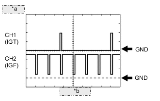
*a 2 V/DIV. *b 20 ms./DIV. Reference: Inspection using an oscilloscope
-
While idling the engine, check the waveform between terminals IGT (1 to 4) and E1, and IGF1 and E1 of the ECM connector.
ECM Terminal Name CH1: Between IGT (1 to 4) and E1
CH2: Between IGF1 and E1
Tester Range 2 V/DIV., 20 ms./DIV. Condition Idling
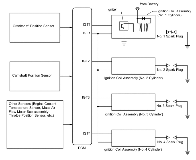
MONITOR DESCRIPTION
A Direct Ignition System (DIS) is used on the engine. The DIS improves the ignition accuracy, reduces high-voltage loss, and enhances the reliability of the ignition system. The DIS is a 1-cylinder system that ignites one cylinder with one ignition coil. The ECU determines the ignition timing and outputs the ignition signals (IGT) for each cylinder. Based on IGT signals, the power transistor in the igniter cuts off the current to the primary coil, which induces a spark at the spark plug connected to the secondary coil. The igniter will also send an ignition confirmation signal (IGF) as a fail-safe measure to the ECU.
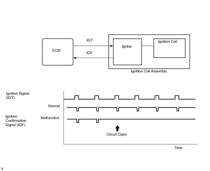
If the ECM does not receive any IGF signals despite transmitting the IGT signal, it interprets this as a fault in the igniter and stores a DTC.
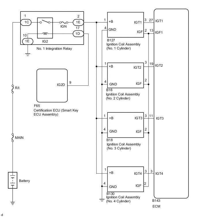
WIRING DIAGRAM
CAUTION / NOTICE / HINT
Tech Tips
-
These DTCs indicate malfunctions relating to the primary circuit.
-
If DTC P0351 is output, check the Ignition coil assembly (No. 1 cylinder) circuit.
-
If DTC P0352 is output, check the Ignition coil assembly (No. 2 cylinder) circuit.
-
If DTC P0353 is output, check the Ignition coil assembly (No. 3 cylinder) circuit.
-
If DTC P0354 is output, check the Ignition coil assembly (No. 4 cylinder) circuit.
-
Read freeze frame data using the GTS. The ECM records vehicle and driving condition information as freeze frame data the moment a DTC is stored. When troubleshooting, freeze frame data can help determine if the vehicle was moving or stationary, if the engine was warmed up or not, if the air fuel ratio was lean or rich, and other data from the time the malfunction occurred.
PROCEDURE
-
READ OUTPUT DTC (IN ADDITION TO IGNITION COIL CIRCUIT)
-
Connect the GTS to the DLC3.
-
Turn the engine switch on (IG).
-
Turn the GTS on.
-
Clear the DTC after recording the freeze frame data and DTC.
-
Turn the engine switch off and wait for at least 30 seconds.
-
Turn the engine switch on (IG) and wait 5 seconds.
-
Turn the GTS on.
-
Enter the following menus: Powertrain / Engine / Trouble Codes.
-
Read the DTCs.
Result Result Proceed to DTC P0351, P0352, P0353 and/or P354 is output A DTCs are not output B
B 
CHECK FOR INTERMITTENT PROBLEMS Click here
A 
-
-
CHECK HARNESS AND CONNECTOR (IGNITION COIL ASSEMBLY - BODY GROUND)
-
Disconnect the B127, B128, B129, and B130 ignition coil assembly connector.
-
Measure the resistance according to the value(s) in the table below.
Standard Resistance Tester Connection Condition Specified Condition B127-4 (GND) - Body ground Always Below 1 Ω B128-4 (GND) - Body ground Always Below 1 Ω B129-4 (GND) - Body ground Always Below 1 Ω B130-4 (GND) - Body ground Always Below 1 Ω Result Proceed to OK NG
NG
REPAIR OR REPLACE HARNESS OR CONNECTOR
OK
-
-
CHECK TERMINAL VOLTAGE (POWER SOURCE OF IGNITION COIL ASSEMBLY)
-
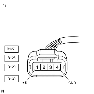
*a Front view of wire harness connector
(to Ignition Coil Assembly)
Disconnect the B127, B128, B129, and B130 ignition coil assembly connector.
-
Turn the engine switch on (IG).
-
Measure the voltage according to the value(s) in the table below.
Standard Voltage Tester Connection Switch Condition Specified Condition B127-1 (+B) - B127-4 (GND) Engine switch on (IG) 11 to 14 V B128-1 (+B) - B128-4 (GND) Engine switch on (IG) 11 to 14 V B129-1 (+B) - B129-4 (GND) Engine switch on (IG) 11 to 14 V B130-1 (+B) - B130-4 (GND) Engine switch on (IG) 11 to 14 V Result Proceed to OK NG
NG
REPAIR OR REPLACE HARNESS OR CONNECTOR
OK
-
-
CHECK HARNESS AND CONNECTOR (IGNITION COIL ASSEMBLY - ECM)
-
Disconnect the B127, B128, B129, and B130 ignition coil assembly connector.
-
Disconnect the B143 ECM connector.
-
Measure the resistance according to the value(s) in the table below.
Standard Resistance Tester Connection Condition Specified Condition B127-2 (IGF) - B143-13 (IGF1) Always Below 1 Ω B128-2 (IGF) - B143-13 (IGF1) Always Below 1 Ω B129-2 (IGF) - B143-13 (IGF1) Always Below 1 Ω B130-2 (IGF) - B143-13 (IGF1) Always Below 1 Ω B127-3 (IGT1) - B143-27 (IGT1) Always Below 1 Ω B128-3 (IGT2) - B143-19 (IGT2) Always Below 1 Ω B129-3 (IGT3) - B143-11 (IGT3) Always Below 1 Ω B130-3 (IGT4) - B143-3 (IGT4) Always Below 1 Ω B127-2 (IGF) or B143-13 (IGF1) - Body ground and other terminals Always 10 kΩ or higher B128-2 (IGF) or B143-13 (IGF1) - Body ground and other terminals Always 10 kΩ or higher B129-2 (IGF) or B143-13 (IGF1) - Body ground and other terminals Always 10 kΩ or higher B130-2 (IGF) or B143-13 (IGF1) - Body ground and other terminals Always 10 kΩ or higher B127-3 (IGT1) or B143-27 (IGT1) - Body ground and other terminals Always 10 kΩ or higher B128-3 (IGT2) or B143-19 (IGT2) - Body ground and other terminals Always 10 kΩ or higher B129-3 (IGT3) or B143-11 (IGT3) - Body ground and other terminals Always 10 kΩ or higher B130-3 (IGT4) or B143-3 (IGT4) - Body ground and other terminals Always 10 kΩ or higher Result Proceed to OK NG
NG
REPAIR OR REPLACE HARNESS OR CONNECTOR
OK
-
-
CHECK WHETHER DTC OUTPUT RECURS (DTC P0351, P0352, P0353 OR P0354)
-
Connect the GTS to the DLC3.
-
Turn the engine switch on (IG).
-
Turn the GTS on.
-
Clear the DTCs.
-
Shuffle the arrangement of the ignition coil assemblies (among No. 1 to No. 4 cylinders).
Note
Do not change the location of the connectors.
-
Perform a simulation test.
-
Enter the following menus: Powertrain / Engine / Trouble Codes.
-
Read the DTCs.
Result Result Proceed to Same DTC output A Different ignition coil DTC output B
A
REPLACE ECM Click here
B
REPLACE IGNITION COIL ASSEMBLY Click here
-