SFI SYSTEM, Diagnostic DTC:P0341
| DTC Code | DTC Name |
|---|---|
| P0341 | Camshaft Position Sensor "A" Circuit Range / Performance Bank 1 or Single Sensor |
DESCRIPTION
| DTC No. | Detection Item | DTC Detection Condition | Trouble Area | MIL | Memory |
|---|---|---|---|---|---|
| P0341 | Camshaft Position Sensor "A" Circuit Range / Performance Bank 1 or Single Sensor | DTC Detection Condition
Enable Criteria
Malfunction Criteria
Diagnostic Mask
Monitor
Potential failure modes |
|
Comes on | DTC stored |
MONITOR DESCRIPTION
The camshaft position input to the ECU is used to determine engine phase, enable sequential fuel injection control and to determine camshaft position for VVT control. The inlet camshaft has three 'teeth' spaced 90° apart, which are detected by the electromagnetic sensor. The valve timing set ting is measured in the ECU by measuring time from a (fixed position) crankshaft tooth to a (variable position) camshaft tooth. As the engine speed and the position is known from the crankshaft sensor signal, the camshaft position can be calculated.
WIRING DIAGRAM
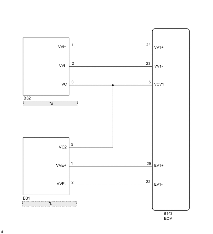
| *a | Camshaft Position Sensor (for Intake Camshaft) |
| *b | Camshaft Position Sensor (for Exhaust Camshaft) |
CAUTION / NOTICE / HINT
Tech Tips
Read freeze frame data using the GTS. Freeze frame data records the engine condition when malfunctions are detected. When troubleshooting, freeze frame data can help determine if the vehicle was moving or stationary, if the engine was warmed up or not, if the air fuel ratio was lean or rich, and other data from the time the malfunction occurred.
PROCEDURE
-
CHECK TERMINAL VOLTAGE (POWER SOURCE OF CAMSHAFT POSITION SENSOR (FOR INTAKE CAMSHAFT))
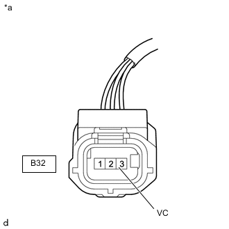
*a Front view of wire harness connector
(to Camshaft Position Sensor (for Intake Camshaft))
-
Disconnect the camshaft position sensor (for intake camshaft) connector.
-
Turn the engine switch on (IG).
-
Measure the voltage according to the value(s) in the table below.
Standard Voltage Tester Connection Switch Condition Specified Condition B32-3 (VC) - Body ground Engine switch on (IG) 4.5 to 5.5 V Result Proceed to OK NG
NG 
CHECK HARNESS AND CONNECTOR (CAMSHAFT POSITION SENSOR (FOR INTAKE CAMSHAFT) - ECM) Click here
OK 
-
-
CHECK HARNESS AND CONNECTOR (CAMSHAFT POSITION SENSOR (FOR INTAKE CAMSHAFT) - ECM)
-
Disconnect the B32 camshaft position sensor (for intake camshaft) connector.
-
Disconnect the B143 ECM connector.
-
Measure the resistance according to the value(s) in the table below.
Standard Resistance Tester Connection Condition Specified Condition B32-1 (VVI+) - B143-24 (VV1+) Always Below 1 Ω B32-2 (VVI-) - B143-23 (VV1-) Always Below 1 Ω B32-1 (VVI+) or B143-24 (VV1+) - Body ground and other terminals Always 10 kΩ or higher B32-2 (VVI-) or B143-23 (VV1-) - Body ground and other terminals Always 10 kΩ or higher Result Proceed to OK NG
NG 
REPAIR OR REPLACE HARNESS OR CONNECTOR
OK
-
-
CHECK CAMSHAFT POSITION SENSOR (FOR INTAKE CAMSHAFT) INSTALLATION
-
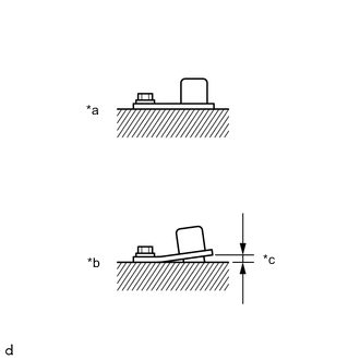
*a OK *b NG *c Clearance Check the camshaft position sensor (for intake camshaft) installation condition.
OK Camshaft position sensor (for intake camshaft) is installed correctly. Result Proceed to OK NG
NG
SECURELY REINSTALL CAMSHAFT POSITION SENSOR (FOR INTAKE CAMSHAFT) Click here
OK
-
-
INSPECT CAMSHAFT (TIMING ROTOR)
-
Inspect the teeth of the camshaft.
OK The teeth do not have any cracks or deformation. Result Proceed to OK NG
NG
REPLACE CAMSHAFT (FOR INTAKE CAMSHAFT) Click here
OK
-
-
REPLACE CAMSHAFT POSITION SENSOR (FOR INTAKE CAMSHAFT)
-
Replace the camshaft position sensor (for intake camshaft).
Result Proceed to NEXT
NEXT
-
-
CHECK WHETHER DTC OUTPUT RECURS (DTC P0341)
-
Connect the GTS to the DLC3.
-
Turn the engine switch on (IG).
-
Turn the GTS on.
-
Clear the DTCs.
-
Turn the engine switch off and wait for at least 30 seconds.
-
Start the engine.
-
Turn the GTS on.
-
Stop the engine and wait for at least 10 seconds.
-
Enter the following menus: Powertrain / Engine / Trouble Codes.
-
Read the DTCs.
Result Result Proceed to DTCs are not output A DTC P0341 is output B
A
END
B
REPLACE ECM Click here
-
-
CHECK HARNESS AND CONNECTOR (CAMSHAFT POSITION SENSOR (FOR INTAKE CAMSHAFT) - ECM)
-
Disconnect the B32 camshaft position sensor connector (for intake camshaft).
-
Disconnect the B143 ECM connector.
-
Measure the resistance according to the value(s) in the table below.
Standard Resistance Tester Connection Condition Specified Condition B32-3 (VC) - B143-5 (VCV1) Always Below 1 Ω B32-3 (VC) or B143-5 (VCV1) - Body ground and other terminals Always 10 kΩ or higher Result Proceed to OK NG
OK
REPLACE ECM Click here
NG
REPAIR OR REPLACE HARNESS OR CONNECTOR
-