SFI SYSTEM, Diagnostic DTC:P0327, P0328
| DTC Code | DTC Name |
|---|---|
| P0327 | Knock Sensor 1 Circuit Low Bank 1 or Single Sensor |
| P0328 | Knock Sensor 1 Circuit High Bank 1 or Single Sensor |
DESCRIPTION
| DTC No. | Detection Item | DTC Detection Condition | Trouble Area | MIL | Memory |
|---|---|---|---|---|---|
| P0327 | Knock Sensor 1 Circuit Low Bank 1 or Single Sensor | DTC Detection Condition
Enable Criteria
Malfunction Criteria
Diagnostic Mask
Monitor
Potential failure modes |
|
Comes on | DTC stored |
| P0328 | Knock Sensor 1 Circuit High Bank 1 or Single Sensor | DTC Detection Condition
Enable Criteria
Malfunction Criteria
Diagnostic Mask
Monitor
Potential failure modes |
|
Comes on | DTC stored |
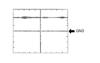
Reference: Inspection using an oscilloscope
Tech Tips
The correct waveform is as shown.
| ECM Terminal Name | Between KNK1 and EKNK |
| Tester Range | 1 V/DIV., 1 ms./DIV. |
| Condition | Engine speed maintained at 4000 rpm after warming up engine |
MONITOR DESCRIPTION
The knock sensor contains a piezoelectric element which generates a voltage when it becomes deformed. The piezoelectric element sends continuously sends a signal to the ECU, when the cylinder block vibrates due to engine knocking this signal increases. The ECU is able to identify each cylinder. If knock is detected then the ECU will retard the ignition of the relevant cylinder to suppress it.The knock control sensor cannot differentiate between spark knock and other similar sounding noises.
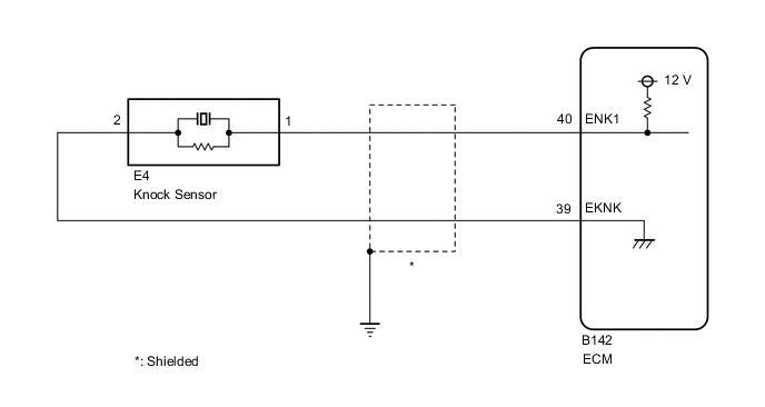
WIRING DIAGRAM
CAUTION / NOTICE / HINT
Tech Tips
Read freeze frame data using the GTS. The ECM records vehicle and driving condition information as freeze frame data the moment a DTC is stored. When troubleshooting, freeze frame data can help determine if the vehicle was moving or stationary, if the engine was warmed up or not, if the air fuel ratio was lean or rich, and other data from the time the malfunction occurred.
PROCEDURE
-
READ VALUE USING GTS (KNOCK FEEDBACK VALUE)
-
Connect the GTS to the DLC3.
-
Start the engine.
-
Turn the GTS on.
-
Warm up the engine.
-
Enter the following menus: Powertrain / Engine / Data List / Knock Feedback Value.
-
Read the values displayed on the GTS while driving the vehicle.
OK The value changes. Tech Tips
Malfunction does not occur Knock Feedback Value changes Malfunctions occur Knock Feedback Value does not change The Knock Feedback Value change can be confirmed by running the engine with a high load, for example, by activating the air conditioning system and racing the engine.
Result Proceed to OK NG
OK 
CHECK FOR INTERMITTENT PROBLEMS Click here
NG 
-
-
CHECK TERMINAL VOLTAGE (POWER SOURCE OF KNOCK SENSOR)
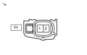
*a Front view of wire harness connector
(to Knock Sensor)
-
Disconnect the knock sensor connector.
-
Turn the engine switch on (IG).
-
Measure the voltage according to the value(s) in the table below.
Standard Voltage Tester Connection Switch Condition Specified Condition E4-2 - E4-1 Engine switch on (IG) 4.5 to 5.5 V Result Proceed to OK NG
NG 
CHECK HARNESS AND CONNECTOR (ECM - KNOCK SENSOR) Click here
OK
-
-
INSPECT KNOCK SENSOR
-
Inspect the knock sensor.
Result Proceed to OK NG
OK
REPLACE ECM Click here
NG
REPLACE KNOCK SENSOR Click here
-
-
CHECK HARNESS AND CONNECTOR (ECM - KNOCK SENSOR)
-
Disconnect the B142 ECM connector.
-
Disconnect the E4 knock sensor connector.
-
Measure the resistance according to the value(s) in the table below.
Standard Resistance Tester Connection Condition Specified Condition B142-40 (ENK1) - E4-1 Always Below 1 Ω B142-39 (EKNK) - E4-2 Always Below 1 Ω B142-40 (ENK1) or E4-1 - Body ground and other terminals Always 10 kΩ or higher B142-39 (EKNK) or E4-2 - Body ground and other terminals Always 10 kΩ or higher Result Proceed to OK NG
OK
REPLACE ECM Click here
NG
REPAIR OR REPLACE HARNESS OR CONNECTOR
-